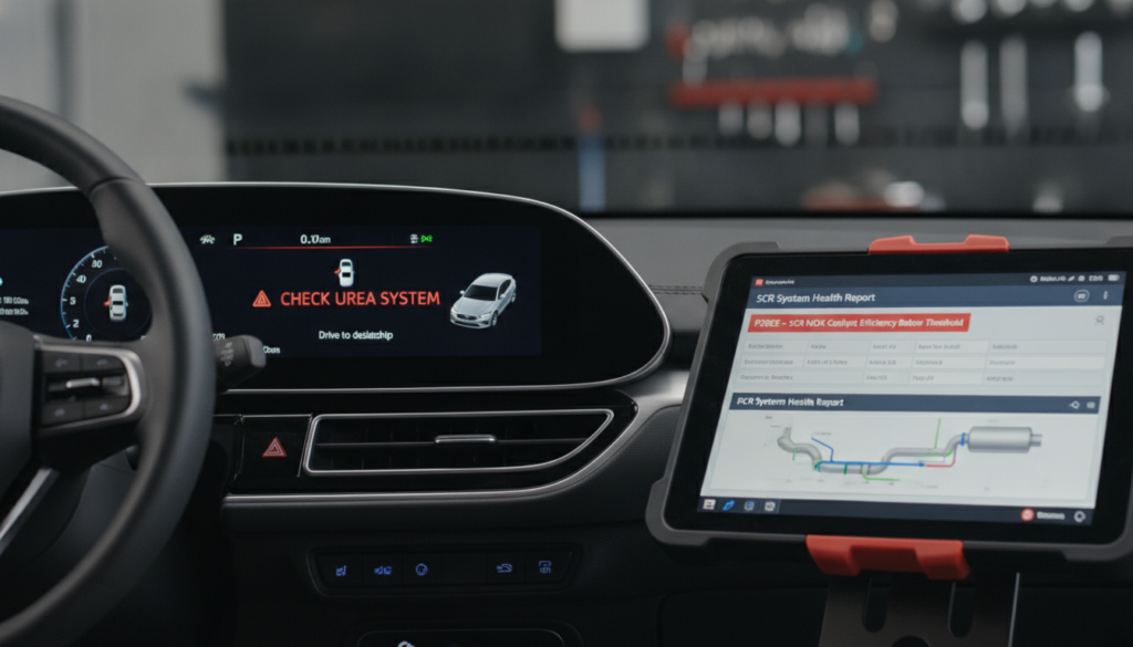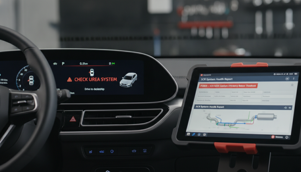
Decoding factory wiring color codes without a verified reference directly threatens your vehicle’s electrical integrity. One misidentified wire can trigger cascading faults, blown fuses, or permanent ECU damage, costing thousands to fix. Most technicians underestimate how deeply manufacturer-specific these systems actually are.
Wiring harnesses use a primary base color paired with a tracer stripe, the circuit’s specific function is revealed only by this exact combination. Because these codes vary by industry, geographic region, and power type, misreading them is hazardous.
This guide breaks down universal conventions, manufacturer-specific differences, tracer-stripe logic, and the step-by-step process for accurately and safely reading any factory wiring chart.
Decoding Factory Wiring Color Codes: The Critical Truth Behind Every Wire
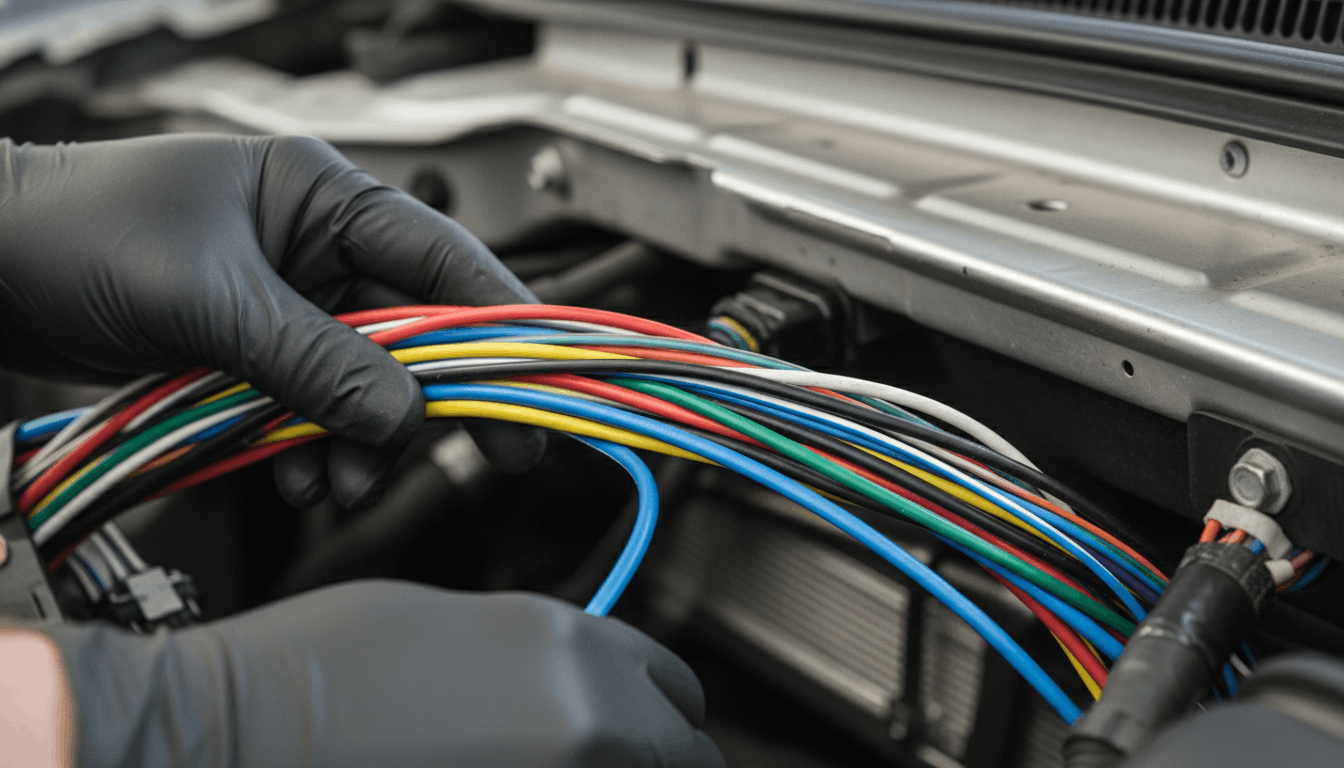
Factory wiring color codes are not universal across the automotive industry. Each manufacturer maintains its own internal standard, and colors shift between model years, trim levels, and regional markets.
Understanding how these codes are built and where they break from common convention, is what separates a clean diagnostic from a costly repair error. Getting this right requires more than a generic online chart.
Universal Color Conventions You Must Know First
Before touching any harness, understanding the base-level color conventions shared across most manufacturers is essential. These are starting points, not absolute rules, and treating them as guarantees will steer your diagnostic in the wrong direction.
Most vehicles share these general factory wiring conventions:
- Black: Chassis ground
- Red: Constant 12V battery power
- Yellow: Switched 12V ignition power (or constant memory in audio circuits)
- White: Lighting and illumination circuits
- Blue: Accessory circuits such as power windows or antenna remote
- Green: Low-voltage signal wires, including sensor outputs and speaker signals
- Orange: Dimmer or illumination feed
These conventions are loosely established by the Society of Automotive Engineers (SAE) for North American vehicles. European and Japanese manufacturers apply their own internal rules, which often contradict these norms entirely.
Always treat these as a framework, not a definitive answer. Never act on color alone without cross-referencing a vehicle-specific factory service manual or verified wiring diagram.
For tracing deeper electrical faults, pairing this knowledge with proper wiring diagrams to trace shorts gives you a far more complete and reliable diagnostic picture.
How Stripe Tracers Change Everything You Assumed

The stripe tracer system is where most non-specialists make their biggest and most costly errors. A solid red wire and a red wire with a white stripe are entirely different circuits, even though they share the same base color.
The naming convention always lists the base color first, followed by the tracer stripe color. Red/White means a red wire with a thin white stripe running along its length. Red/Black is a completely separate circuit with a different function.
Key points on tracer logic every technician must know:
- A Red/White wire may indicate a specific ignition-switched circuit
- A Red/Black wire often signals a fused constant power feed
- A Green/White wire in a Honda harness may control an antenna relay
- A Blue/Black wire in a Toyota harness may indicate a dedicated ECU signal line
Missing the tracer stripe means you are diagnosing the wrong circuit entirely. If you are working near the engine control unit, always pair your color code reading with ecu pinout charts explained for diagnostics to confirm pin assignments before testing any live circuit.
Manufacturer Color Codes: Ford vs GM vs Toyota vs Honda
No two manufacturers share a completely identical factory wiring color code map. Even where colors overlap, the circuit assignments differ. The table below shows how key wire colors translate across major automotive brands:
|
Wire Color |
Ford |
GM |
Toyota |
Honda |
|
Black |
Ground |
Ground |
Ground |
Ground |
|
Red |
Constant Power |
Constant Power |
Constant Power |
Constant Power |
|
Yellow |
Memory/Constant |
Ignition-Switched |
Constant 12V |
Constant 12V |
|
Green |
Signal/Sensor |
Signal |
Signal |
Speaker/Signal |
|
Blue |
Accessory |
Accessory |
ECU Signal |
Power Antenna |
|
Orange |
Illumination |
Illumination |
Illumination |
Illumination |
|
Pink |
N/A |
N/A |
N/A |
Speed Signal |
The model year factor is critical here. GM harnesses from a 2015 model may use entirely different tracer combinations than a 2019 version of the same vehicle line. Trim level and installed options also alter the harness, since a premium audio package requires additional wiring that a base model does not carry.
Regional differences add yet another layer. In the Japanese Domestic Market, Toyota uses different color codes than the North American export version of the same vehicle. Never assume a chart from an online forum applies to your exact configuration without first confirming the market, trim, and model year.
Reading a Factory Wiring Chart Step by Step

Factory wiring charts follow a consistent internal logic once you understand their structure. Here is the exact process experienced technicians use on every diagnostic job.
Step 1: Identify the circuit you are diagnosing. Locate the component in the factory service manual index and find its corresponding circuit number or page in the diagram.
Step 2: Locate the connector on the diagram. Factory diagrams show every connector with an alphanumeric ID, typically formatted as C105 or E0220, and these must match the physical connector on the vehicle.
Step 3: Match the base color and tracer stripe. Read the full wire designation, base color followed by the stripe, and cross-reference it to the color code legend within the same manual page.
Step 4: Confirm the wire function with a multimeter. Before cutting or splicing anything, verify the wire’s function electrically. Check for constant voltage, switched voltage, or signal continuity as specified in the diagram.
Step 5: Cross-reference relay circuits where applicable. Many factory circuits route through relays before reaching the final component. Understanding the relay path prevents false fault readings. For this step, reviewing relay testing procedures manual pinouts will help validate each relay-controlled leg of the circuit with precision.
Common Mistakes That Damage Your Electrical System
Even experienced technicians fall into predictable traps when reading factory wiring color codes. Recognizing these pitfalls ahead of time protects both your diagnostic accuracy and the vehicle.
Relying on aftermarket color charts for OEM diagnostics. Aftermarket radio harnesses use a standardized color system that does not match factory codes. Applying an aftermarket chart to an OEM harness will produce incorrect wire identification every single time.
Ignoring trim-level and option-related harness changes. A vehicle with a factory-amplified audio system has a completely different harness layout from the base model. Misreading the harness in accessory circuits can also affect related systems, including power windows wiring schematics, which often share connector zones near the door modules.
Assuming previous repair work preserved factory colors. Aftermarket splices, replaced connectors, and prior electrical repairs frequently introduce non-factory wire colors into the harness. Always test electrically before trusting color identification alone on any vehicle with a repair history.
Conclusion
Factory wiring color codes are a structured system built on base colors, tracer stripes, manufacturer-specific standards, and model-year variables. Each element is part of the wire’s identity, and reading only part of that identity leads to the wrong diagnosis.
The right approach is always to source the factory service manual for your exact year and trim, confirm every wire electrically before touching it, and never trust color alone. Master that process, and your diagnostic accuracy will improve on every job you take.
Frequently Asked Questions
No, factory wiring color codes are not standardized across the automotive industry. Ford, GM, Toyota, Honda, and other brands each maintain their own internal color systems. While some conventions overlap, such as black for ground and red for constant battery power, the assignments for signal wires, accessory circuits, and control lines differ significantly between brands.
Model year changes add further variation, meaning even the same make can use different color combinations across production years. Always consult the factory service manual for your specific vehicle’s year, make, model, and trim before diagnosing or modifying any circuit.
A stripe or tracer is a thin, colored line running along the length of a wire’s base color. It exists because vehicles contain hundreds of wires, and using solid colors alone is not enough to uniquely identify each circuit. The tracer refines the wire’s identity beyond the base color, and the two must always be read together.
A Green wire and a Green/White wire serve completely different functions. The naming convention lists the base color first, then the tracer. Misreading the tracer is one of the most common diagnostic errors in automotive electrical work.
The most reliable source is the factory service manual specific to your vehicle’s year, make, model, and trim level. These manuals include complete wiring diagrams with accurate color code legends for every circuit in the system.
Haynes and Chilton manuals are a secondary option, but are generally less detailed than OEM documentation. Online subscription databases such as Mitchell1 and ALLDATA provide digital access to OEM-level wiring diagrams for most makes and models.
Avoid relying on generic internet color code charts or forum posts, as these are frequently inaccurate for specific configurations.
Yes, manufacturers regularly update wiring harness designs between model years, and color codes often change as a result. Updated electronics packages, new safety systems, and revised engine management technology all require harness modifications that impact wire color assignments.
A color code that correctly identifies a circuit on a 2016 model may be entirely wrong for the 2019 version of the same vehicle. Always verify the model year on your reference material before beginning any diagnostic or repair work on the electrical system to avoid misidentification.
A quality digital multimeter is the most essential tool for verifying voltage, continuity, and signal behavior before and after identifying a wire by color alone. A factory service manual or OEM-level wiring diagram is required for accurate reference in every job.
A wiring diagram software subscription adds depth for complex multi-harness systems. A wire tracer or tone generator helps locate specific circuits when visual identification is difficult due to harness bundling or prior repairs that altered wire routing.
Combining these tools with verified factory color code information ensures accurate diagnostics without unnecessary risk to the vehicle’s electrical system.