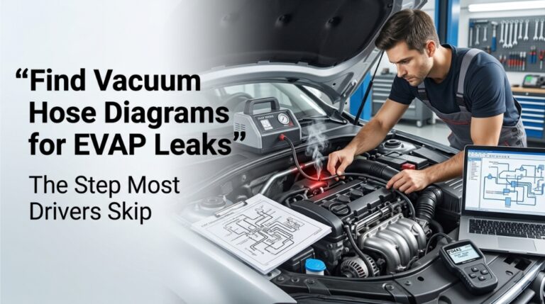
Chasing EVAP leaks like P0442 or P0455 without a vacuum hose diagram can lead to hours of wasted inspection time. Since codes only indicate a system fault, not a location, a precise map is essential to avoid missing the actual leak.
To locate a leak, trace hoses outward from the charcoal canister using a factory diagram. This maps the circuit from the intake manifold and purge valve to the fuel tank. Focus on likely failure points, such as the purge valve, filler neck, or hoses near the canister.
This guide explains how to find vehicle-specific diagrams, interpret the EVAP layout, and isolate leaks without unnecessary parts replacement.
Find Vacuum Hose Diagrams for EVAP Leaks: Where the Correct Map Changes Everything
Tracing EVAP hose paths without a diagram turns simple emissions repairs into lengthy diagnostic chores. Because manufacturers vary layouts, this network linking the tank, canister, and valves via vacuum lines requires a vehicle-specific map for accuracy.
A factory diagram details exact paths and flow directions. Without it, interpreting a smoke test is difficult; while smoke may be visible, you cannot easily identify which specific circuit is leaking without the routing map.
Step 1: Read the DTC First — It Narrows the Diagram Section
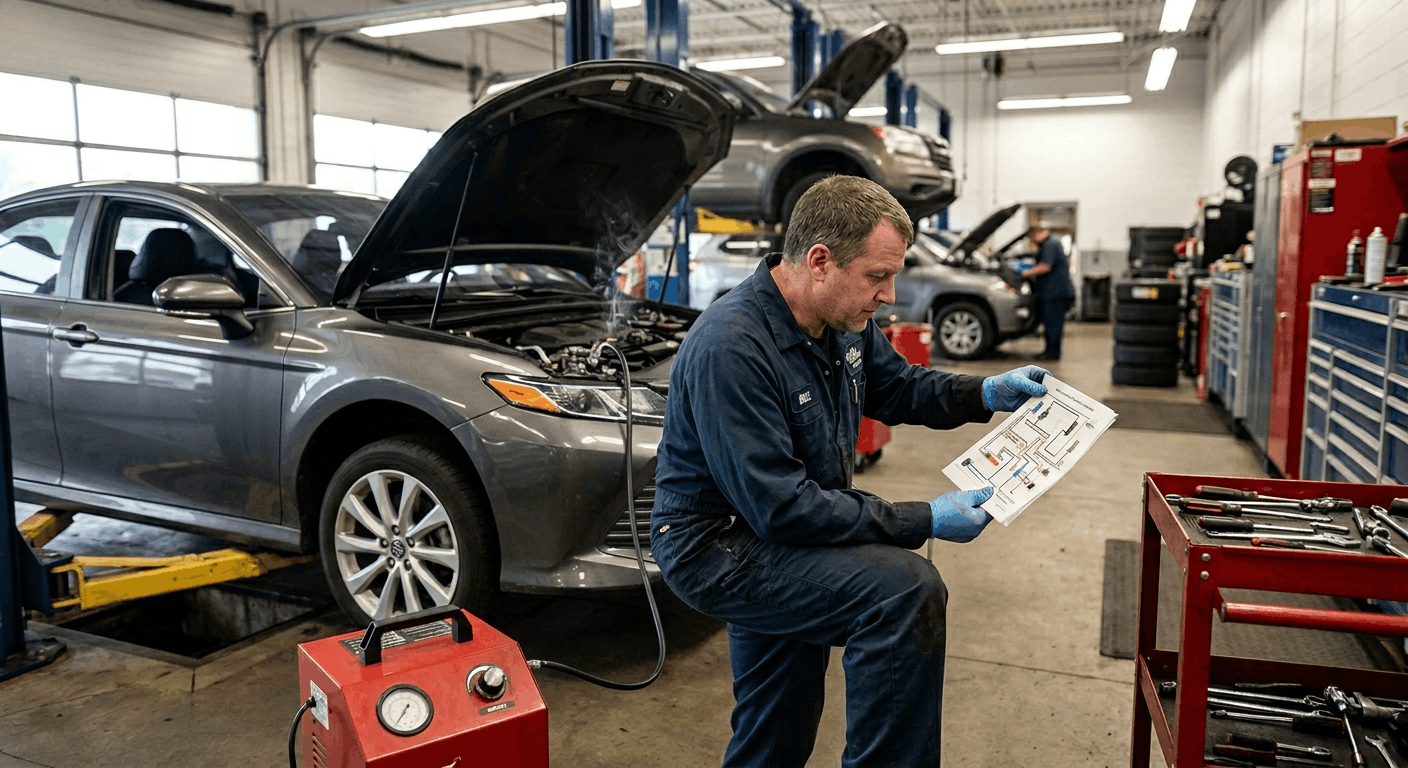
Before searching for any diagram, the fault code narrows the search to a specific part of the EVAP system. Knowing which code is active tells you which circuit to focus on in the routing diagram — this saves significant time.
Common EVAP DTCs and what they indicate:
|
DTC Code |
System Fault |
Primary Hose Circuit to Check |
|
P0440 |
EVAP system malfunction |
The entire system starts with the canister and purge valve |
|
P0441 |
Incorrect purge flow |
Purge valve, vacuum line, and purge solenoid connector |
|
P0442 |
Small evaporative leak (0.020″ or less) |
Hose joints, clamps, and O-rings throughout the system |
|
P0455 |
Gross evaporative leak (large) |
Gas cap, filler neck, and main canister hose connections |
|
P0446 |
Vent control circuit |
Canister vent valve line and vent solenoid vacuum circuit |
Gross leak codes like P0455 highlight major failures in the gas cap, filler neck hose, or canister line. Conversely, P0442 small leaks require precise inspection for hairline cracks or worn O-rings. A factory diagram identifies both large and small circuit paths, directing your initial search.
EPA data shows that 70% of EVAP leaks stem from component deterioration, such as aged rubber hoses and cracked connectors, while 30% stem from external issues, such as faulty gas caps. Diagrams prioritize these common deterioration points for more efficient diagnosis.
Step 2: Locate the Right Vacuum Hose Diagram for Your Vehicle
This is the step most people either skip or approach incorrectly. Using a generic EVAP diagram found online for a similar model year often shows the wrong hose routing — manufacturers change vacuum layouts between trims, engine variants, and production years without changing the body style.
Three places to find the correct vehicle-specific EVAP vacuum diagram:
Under-hood emissions label: Most vehicles manufactured after 1980 include a vacuum routing sticker affixed to the radiator support, underside of the hood, or fan shroud. This label is year-, engine-, and emissions-package-specific.
It shows the complete EVAP and engine vacuum routing for that exact build. If the label is intact, it is the fastest reference available because it reflects what was physically installed at the factory.
Factory service manual: The full factory service manual contains the most detailed vacuum hose diagrams for every subsystem. For EVAP systems, this typically appears in the Emissions or Engine Controls section and includes component locations, hose diameters, routing paths, and solenoid positions.
Factory diagrams differentiate between standard and California-emissions variants, which often have different canister sizes and additional hose connections.
OEM-level repair database: Manufacturer-authorized repair databases such as ALLDATA and Mitchell ProDemand contain the same factory diagrams used by dealership technicians. These are searchable by VIN, which eliminates the risk of using a slightly incorrect variant.
For guidance on where to download verified, year-specific factory service documentation for your vehicle before starting any EVAP leak diagnosis, this resource, “Where to Download Genuine OEM Workshop Manuals,” is a practical starting point.
Step 3: Read the EVAP Diagram — Trace Every Hose in Sequence
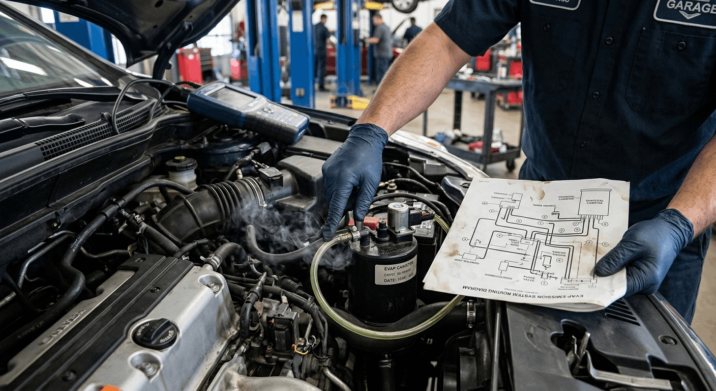
A vacuum hose diagram for an EVAP system shows several distinct circuits running between five core components. Understanding the function of each circuit helps you trace leaks logically rather than randomly.
The five core EVAP components are shown in factory diagrams:
- Fuel tank: The origin of fuel vapor — the diagram shows vent lines from the tank to the charcoal canister and the rollover valve position
- Charcoal canister: The carbon storage unit that absorbs fuel vapor — the diagram shows the vent line in, the purge line out, and the vent valve connection at the base
- Purge valve solenoid: The ECU-controlled valve that allows stored vapors to enter the intake under specific conditions — the diagram shows two hose connections: one to the canister and one to the intake manifold
- Vent valve: Controls atmospheric pressure entry into the canister — the diagram shows its position near the canister and the vent hose routing
- Intake manifold connection: The endpoint for purged vapors — the diagram shows where the purge hose connects to the intake, either upstream or downstream of the throttle body
When tracing the diagram against the physical vehicle, start at the charcoal canister and work outward in both directions toward the fuel tank and toward the purge valve. This systematic approach ensures no branch hose is missed.
The EVAP hose diagram also indicates hose diameter at each connection point. Using an incorrect-diameter replacement hose on any fitting results in either a restriction or a loose connection, both of which cause leak codes after repair. The diagram eliminates that guesswork entirely.
For technicians deciding between full factory service manuals and aftermarket guides for this type of emissions work, the practical trade-offs are worth understanding before committing to a documentation source: When to Upgrade to a Factory Service Manual.
Step 4: Use the Diagram with a Smoke Test for Precise Leak Location
A vacuum hose diagram and a smoke test are the two most reliable tools for locating EVAP leaks. Each one complements the other. The diagram tells you the circuit layout, and the smoke reveals exactly where the breach is.
Smoke test procedure using the diagram:
- Close the EVAP vent valve using a bidirectional scan tool (Mode $08 data) — this seals the system so smoke pressure is contained
- Connect the smoke machine to the EVAP test port or the fuel filler neck, following the connection point shown in your factory diagram
- Introduce smoke at low pressure — EVAP systems are fragile, and over-pressurization can damage vent valves or canister seals
- Hold your vacuum hose diagram and trace each line in the system visually while smoke is present
- Watch for smoke escaping at hose joints, solenoid connections, canister seams, and the filler neck — any exit point indicates a leak in that location
- Note the position on the diagram — this confirms which circuit the leak belongs to and which replacement part or section of hose is required
Without the diagram during a smoke test, escaping smoke reveals a location but not a circuit. With the diagram, you immediately know which component is upstream of the leak and which line needs to be replaced.
For situations where the EVAP fault appears alongside other warning lights, and you are uncertain whether the check engine light relates to the emissions system or to body electronics, this guide on SRS Airbag Light Reset Steps via OEM Manuals can help cleanly separate those diagnoses.
Step 5: Inspect and Repair Using the Diagram as a Reference Map

With the leak location confirmed via smoke and mapped against the diagram, physical inspection follows a direct path. The diagram tells you the hose specification, the fitting type at each end, and whether a clamp or a press-fit connector holds the joint.
Physical inspection checklist for EVAP hose leaks:
- Rubber vacuum hoses: Look for cracks, splits, or brittleness at the ends where the hose meets the fitting. Aged rubber develops surface cracking that opens under vacuum pressure during system testing, but may look intact under static inspection
- Plastic connectors and quick-connect fittings: Press-fit connectors crack at the locking tabs over time. The diagram shows every connector location. Check each one by pressing inward and pulling gently to confirm the lock is intact
- O-rings at solenoid ports: Purge valve and vent valve solenoids use O-ring seals at their port connections. These harden and crack with age and produce small leaks that pass visual inspection but fail the smoke test
- Canister body seams: Charcoal canisters on high-mileage vehicles can develop hairline cracks at the seam between the upper and lower housing, visible under smoke but not under visual inspection alone
- Gas cap and filler neck: A P0455 gross leak code should prompt an inspection of the gas cap seal first. Press the cap firmly, listen for the click, and verify the seal ring is intact and undeformed
The distinction between a factory diagram and an aftermarket guide becomes critical during this inspection phase. Aftermarket manuals sometimes show generalized EVAP layouts that omit California-spec components, regional variants, or mid-production changes. This comparison of Digital Car Manuals vs. Mechanic Advice covers when factory-level documentation is the necessary standard for emissions-related repairs.
For those still evaluating which type of workshop documentation best suits their repair level, this overview of How to Choose the Right Workshop Repair Manual for Your Vehicle provides clear guidance before the next job starts.
Conclusion
EVAP leaks are fixable, but only when you use the correct vacuum hose diagram for your specific vehicle. The DTC code narrows the circuit. The factory diagram maps the exact path. The smoke test reveals the breach. And the physical inspection confirms the component.
Skip any one of those steps, and the repair becomes a series of educated guesses. Use all four together, and the job finishes the first time, with no repeated codes and no unnecessary parts replaced.
Frequently Asked Questions
Yes, and it is the most common cause of a gross EVAP leak code. The gas cap is part of the sealed EVAP system. When the PCM runs a leak detection test, it pressurizes or applies a vacuum to the entire system, including the fuel tank and filler neck.
A gas cap with a degraded seal ring, an incorrect part number, or an improper seating allows that pressure to escape immediately, which the system interprets as a gross leak.
Replacing the cap with a correct OEM-spec unit and clearing the code is always the first step before any further EVAP diagnosis on a P0455. If the code returns after 2 to 3 drive cycles with the new cap, a physical hose or component leak exists in the system.
A P0455 gross leak is typically large enough to be detected by visual inspection or a basic smoke test, a disconnected hose, a missing gas cap, or a cracked canister with an obvious opening. A P0442 small leak is a breach of 0.020 inches or less and requires a calibrated smoke machine at the correct low pressure to reveal.
The location also differs statistically: P0455 codes most often trace to the gas cap, filler neck, or main canister hose connections. P0442 codes more commonly trace to aging O-rings, micro-cracks in smaller vacuum lines, or hairline cracks at plastic connector locking tabs.
Your factory vacuum hose diagram is essential for P0442 diagnosis, specifically, because the potential leak points are distributed throughout the system.
Yes, often significantly. California emissions regulations require enhanced EVAP systems that include additional vapor recovery components, larger charcoal canisters, and, in some cases, a second vent valve or a separate leak detection pump assembly.
These differences change the vacuum hose routing shown in the diagram, the number of connection points, and the number of solenoids the PCM monitors. Using a standard-emissions EVAP diagram on a California-spec vehicle or vice versa will show the wrong hose routing for several circuits and lead to incorrect inspection conclusions.
Always confirm your vehicle’s emissions package specification before selecting the diagram to use. The VIN can confirm the build specification, and the factory documentation database search by VIN returns the correct variant.
A hand vacuum pump is useful for testing individual EVAP valves, specifically the purge valve and vent valve, to confirm they hold pressure and open/close correctly. When the engine is off, the purge valve should hold vacuum (in the closed position).
When applied to the vent valve, it should hold a vacuum only when the PCM commands the valve closed. What a hand vacuum pump cannot do is pressurize the entire EVAP system to locate a hose leak, as a smoke machine does.
It can help isolate a faulty valve, but finding a cracked hose or deteriorated O-ring in the system circuit requires either smoke testing or a very methodical visual inspection with the vacuum hose diagram as your guide.
A purge valve replacement resolves a P0441 (incorrect purge flow) or a purge valve electrical circuit code. If the EVAP leak code returns after the purge valve is replaced, the original leak was in a different part of the system.
This is one of the most common post-repair comebacks in EVAP diagnosis, a part is replaced based on its association with the code rather than confirmed testing of that specific component. The purge valve is only one of several vacuum connections in the EVAP circuit.
Returning codes after a valve replacement almost always mean the leak is elsewhere in the hose routing, specifically at aged rubber lines, cracked plastic fittings, or a compromised canister. Using the factory vacuum hose diagram to trace every connection in the circuit is the step that prevents this outcome.