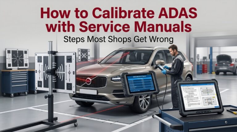
Inaccurate ADAS calibration without service manuals creates liabilities that pass dashboard checks but cause dangerous inaccuracies. A one-degree radar misalignment can lead to significant errors at highway speeds.
Technicians must use OEM-approved manuals to define precise environment, target, and scan tool parameters for specific vehicle setups. Adherence to these manufacturer-varying procedures is mandatory, using a scan tool to trigger either static target-based or dynamic driving-based calibration.
This guide outlines a six-step workflow, highlights common shop oversights, and explains why the manual, not the scan tool, is the final authority for every procedure.
How to Calibrate ADAS with Service Manuals: What OEM Data Actually Reveals
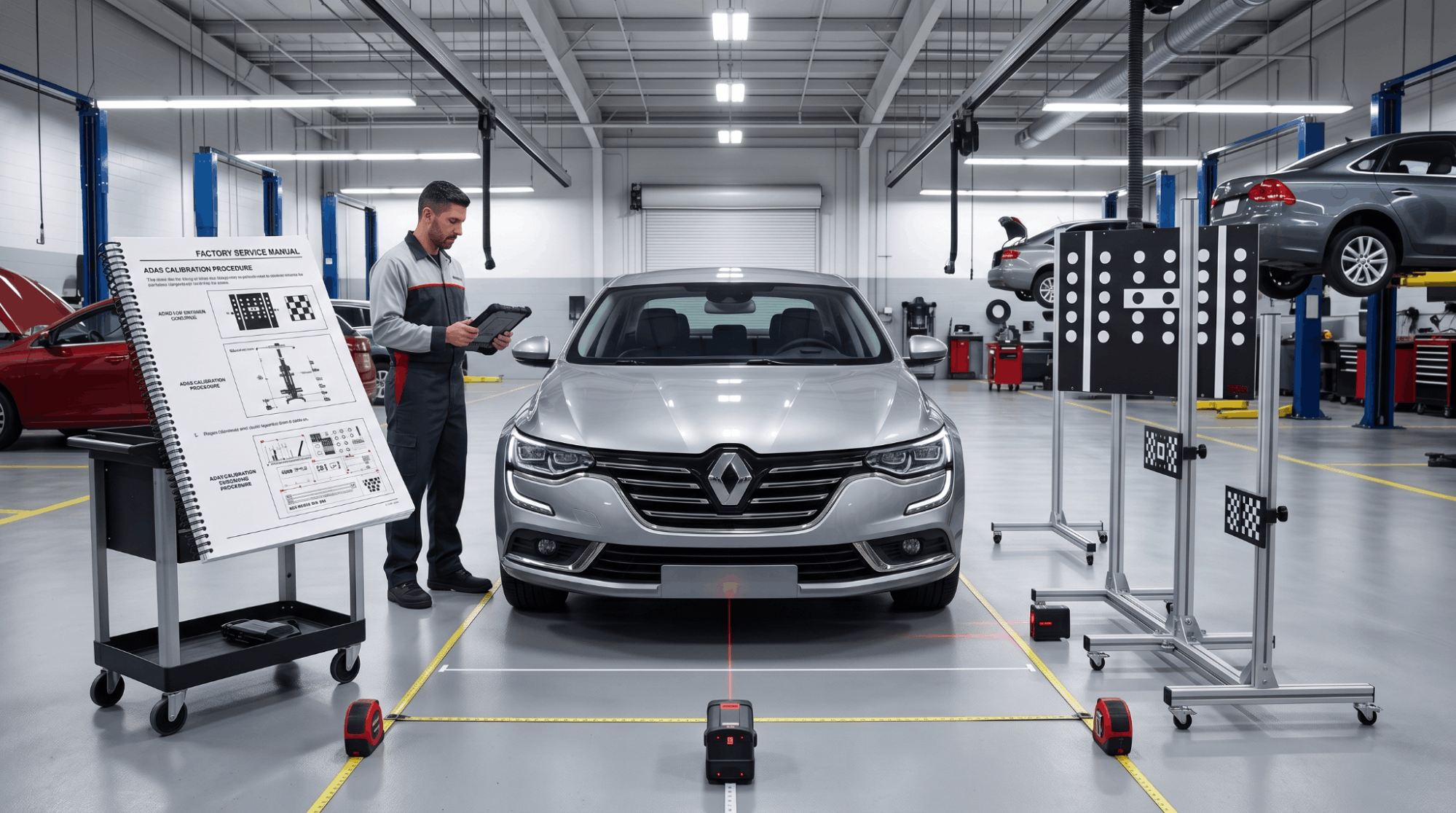
Many technicians underestimate the precision required for ADAS calibration. A factory service manual serves as the definitive calibration protocol, providing OEM-tested data for target measurements, scan tool paths, and verification checks.
Omitting any step jeopardizes the results, often without immediate indication during the procedure.
Step 1: Confirm Your ADAS System Layout First
Before touching any sensor or camera, you need to know exactly which ADAS systems are active in the vehicle. Building sheets and trim packages significantly change the sensor layout, and working from a wrong assumption early costs real diagnostic time later.
Pull the VIN-specific build data from your service manual to confirm:
- Forward collision radar type — bumper-mounted vs. grille-integrated
- Lane departure camera position — top-center windshield vs. mirror-mounted
- Blind-spot monitoring sensor type — ultrasonic vs. radar-based
- Parking assist layout — front-only, rear-only, or full 360-degree
Each system requires a separate calibration procedure with different target specs and scan tool paths. You can
Find your factory service manual PDF by VIN to confirm system specs before any physical work begins.
Skipping this step causes technicians to calibrate at the wrong target angle or use mismatched scan tool parameters from the very start.
Step 2: Clear All Fault Codes Before You Begin
Active fault codes will cause calibration to fail or, more dangerously, appear to succeed while the sensor remains misaligned. The service manual mandates a pre-calibration DTC check as a required first step, not an optional one.
Run a full system scan before attempting any ADAS calibration. Key fault categories to resolve first:
- U-codes: Communication faults between control modules
- C-codes: Chassis sensor issues, especially yaw rate and wheel speed
- B-codes: Body module conflicts affecting camera trigger signals
If you need a structured approach for working through those fault paths,
Reading OBD-II codes using manual flowcharts offers a proven method for fault resolution before any calibration attempt.
An active fault will cause the calibration sequence to abort mid-process, leaving the system in an undefined state.
Step 3: Set Up a Calibration-Ready Environment
ADAS calibration is far more environment-sensitive than most shops expect. OEM service manuals define minimum setup conditions that are easy to overlook but impossible to compensate for afterward.
|
Requirement |
OEM Standard |
|
Floor levelness |
Within 0.5° of flat |
|
Ambient lighting |
300–500 lux minimum |
|
Target distance range |
Model-specific (typically 2–10 meters) |
|
Temperature range |
60°F–95°F (15°C–35°C) |
|
Movement during static calibration |
Zero tolerance |
Set up in a dedicated calibration bay when possible. Reflective surfaces, active HVAC airflow, and moving traffic in the background are all documented interference sources in OEM service documentation.
Ignoring these conditions produces calibration drift that appears within days of completion — not during the procedure itself.
Step 4: Place Targets to Exact Manual Specifications
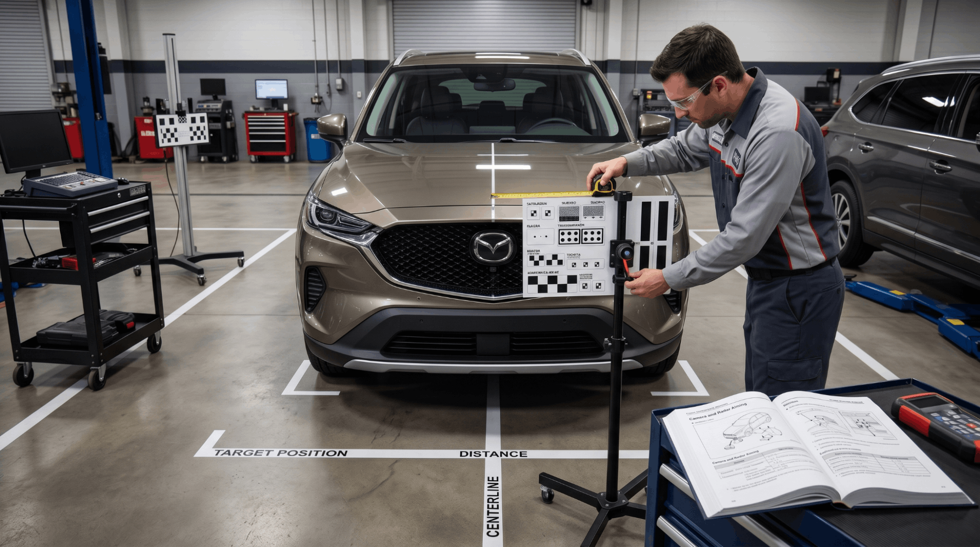
Target placement is where the highest rate of field errors occurs. Service manuals provide precise target dimensions, distances, and height measurements relative to the vehicle’s datum line. These are not approximations, they are load-bearing OEM specifications.
Use the vehicle’s datum line, typically a chassis reference point measured from the ground, to set the target height. The manual specifies:
- Horizontal offset from vehicle centerline in millimeters
- Vertical height from ground level in millimeters
- Distance from the specific sensor — not from the vehicle front bumper edge
Many third-party target boards do not match OEM dimensions for specific models, which creates a calibration offset before the scan tool sequence even starts. For shops questioning whether their current documentation covers this level of detail,
When to upgrade to a factory service manual is worth reviewing before investing in equipment.
Cross-check every target board against the OEM spec for the exact model and trim level being calibrated.
Step 5: Run the Scan Tool Calibration Sequence
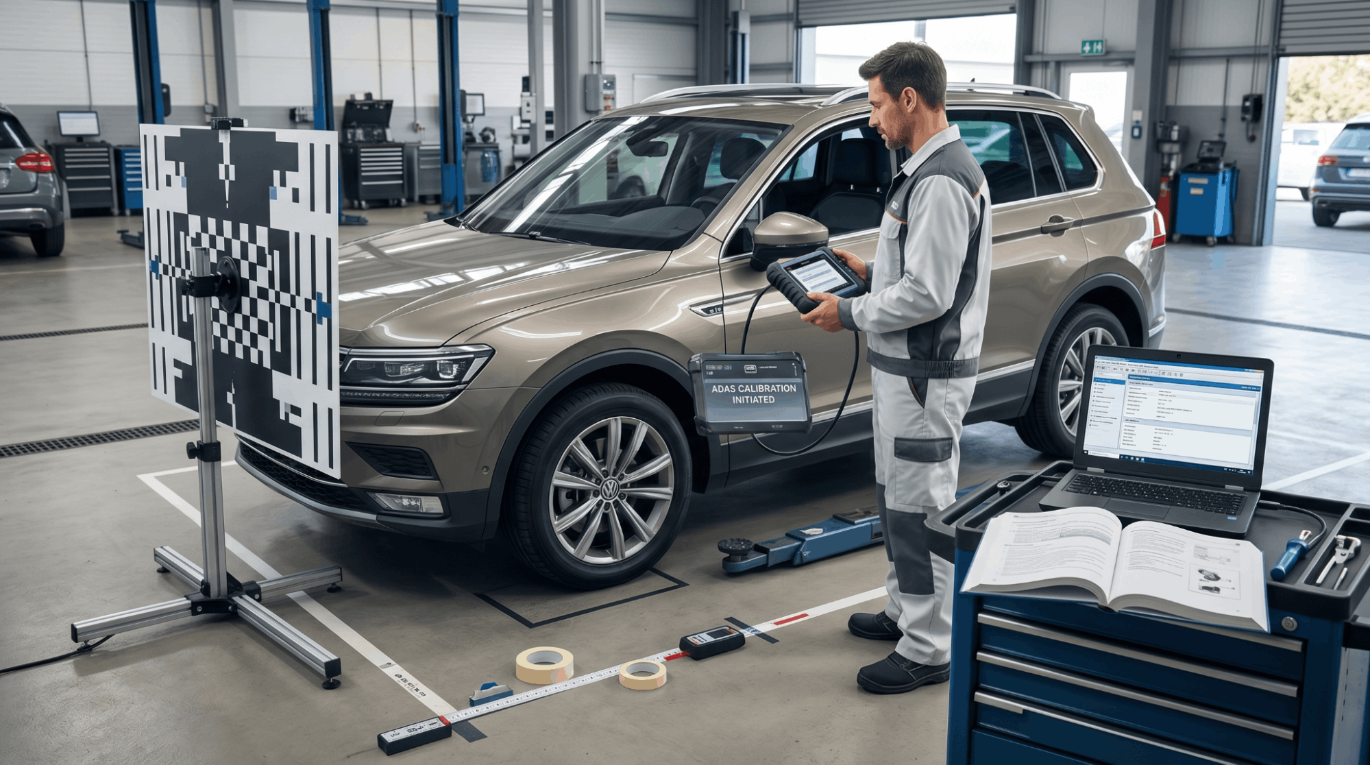
Once the environment is set and targets are correctly positioned, the calibration command is executed through an OEM-level scan tool or a professional aftermarket tool with guided ADAS routines. A basic code reset will not complete this process.
Follow the exact sequence specified in the service manual:
- Navigate to the specific ADAS module — not the generic “all systems” menu
- Select Static or Dynamic Calibration based on what the manual specifies
- Confirm all pre-conditions — doors closed, engine running, or key-on per manual guidance
- Initiate the calibration and do not move the vehicle during the static sequence
- Compare post-calibration output data against OEM acceptance values in the manual
The manual lists exact pass/fail parameters: angle tolerance, distance offset, and signal strength thresholds. If output falls outside those values, re-check target placement before repeating.
When calibration outputs look inconsistent, sensor wiring integrity is often the cause.
ECU pinout charts explained for diagnostics help technicians trace signal-level issues directly at the module.
Step 6: Complete the Dynamic Verification Drive
Static calibration confirms sensor alignment under controlled conditions. A dynamic verification drive confirms the system’s real-world performance. Most OEM service manuals include a required drive cycle with specific parameters for this phase.
Drive cycle requirements typically include:
- Minimum vehicle speed: 30–70 mph, depending on the system type
- Road type: Highway preferred for radar, urban roads for camera-based systems
- Lane marking condition: Clearly painted lines required for LKA and LDW verification
Monitor live data on the scan tool during the drive if your equipment supports it. Post-drive, confirm all ADAS warning indicators are inactive and no new DTCs have appeared.
Always source your service manuals from verified OEM databases for the most complete procedure coverage.
Where to download genuine OEM workshop manuals covers the safest and most complete sources available to professional shops.
Conclusion
Calibrating ADAS without the right service manual is not just inefficient, it is a measurable liability. Every step in this process, from environment setup to dynamic verification, depends on OEM-specific data that generic guides simply cannot provide.
The technicians who get this right consistently resolve fault codes first, use factory service manuals for exact target specifications, and never skip the post-drive verification phase. That is the standard the ADAS system was engineered around, and the only standard that holds up in real-world driving conditions.
Frequently Asked Questions
No. ADAS calibration requires a scan tool with manufacturer-level module access. A basic OBD-II reader cannot initiate the calibration routine or confirm output values against OEM acceptance parameters. Radar-based systems, such as forwardcollision modules, require bidirectional communication to complete the sequence.
Without that scan tool capability, the system may appear functional while still running on factory defaults rather than post-repair calibration data. Always use a scan tool that explicitly lists support for the vehicle’s ADAS module, not just general OBD-II access.
ADAS recalibration is required any time a sensor, camera, or radar module is physically disturbed. That includes windshield replacement, bumper repair, alignment changes, suspension work, and any repair that shifts the sensor’s mounting position.
Some manufacturers also require recalibration after ECU software updates. It is not a scheduled maintenance item it is an event-triggered requirement.
Skipping it after any of those repairs is the most common cause of ADAS failures that never trigger a warning light, making them especially difficult to diagnose after the fact.
Static calibration uses fixed targets placed at precise distances and angles to align sensors while the vehicle is stationary.
Dynamic calibration requires driving under specific conditions so the system self-corrects using real-world lane markings and objects. Many vehicles require both procedures. The service manual specifies which method applies to each individual sensor or camera.
Using dynamic-only calibration when a static step is also required is a documented failure point. The system accepts the dynamic input but retains physical misalignment from the mounting position.
Yes, in most modern vehicles. The front-facing camera used for lane departure, forward collision, and traffic sign recognition is mounted directly to the windshield or to a bracket bonded against it. Replacing the windshield shifts the camera’s aim angle, even by a fraction.
Most OEM service manuals mandate camera recalibration after any windshield replacement, and many insurance policies now include ADAS recalibration as a covered line item for this reason. Skipping this step after windshield work is a growing liability concern across the collision repair industry.
Yes, significantly. Aftermarket bumpers, grilles, and hoods often have slightly different mounting geometries than OEM parts, which can shift the sensor’s effective field of view even after calibration is complete.
The service manual calibration specs are written around OEM part dimensions and tolerances. If an aftermarket bumper positions a radar module even 5mm lower than the factory location, the target distance calculation is off from the start.
For insurance repair work specifically, always verify that replacement parts match OEM mounting dimensions before beginning any ADAS calibration sequence.