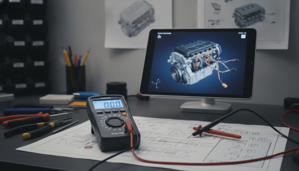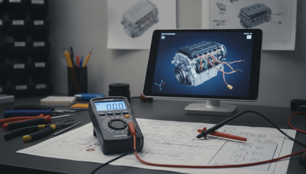
Probing the wrong pin on a Hyundai connector is not a minor mistake. It bends terminals, corrupts signal readings, and can destroy an ECU harness that costs several hundred euros to replace. Most DIY mechanics only realize the problem after the damage is already done.
Accurate Hyundai connector pinouts are found in factory service manuals, not generic online images. Each connector features a numbered pin table linked to a location index that identifies specific harnesses and signals. While Hyundai uses standardized diagnostic layouts, ECM and radio harnesses vary significantly by model, year, and engine specifications.
This post covers how to find your Hyundai connector pinout data, how to read the wiring numbering system, and how to test pins safely without terminal damage. You'll also learn which connectors cause the most DIY problems and how factory documentation solves each one.
Hyundai Connector Pinout Guide: The Factory Source That Makes Testing Reliable
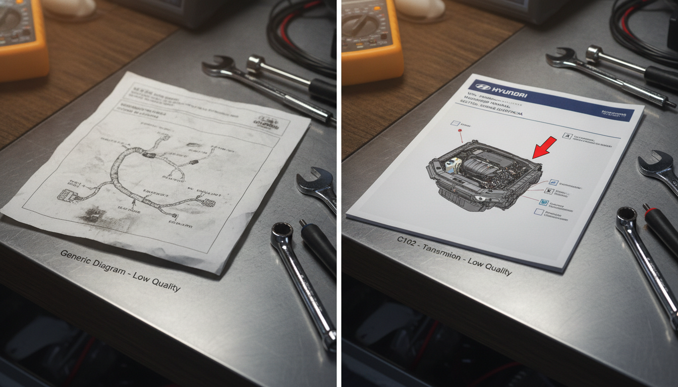
Alter Tag: Comparison between a generic wiring diagram and a VIN-specific Hyundai factory service manual for accurate pinout data.
Generic connector diagrams found through a basic web search almost never match a specific Hyundai model, trim level, or production year. Hyundai produces region-specific harnesses, and a diagram made for a North American Sonata will not match a European ix35 in wiring color, pin count, or connector housing shape.
Owners repeatedly encounter this mismatch when installing aftermarket stereos, testing sensors, or tracing faults. The only reliable source for a Hyundai connector pinout guide is the OEM factory service manual tied to your exact VIN and production year.
That manual contains a full connector location index, numbered pin assignment tables, wire diameter and color codes, and terminal locking type specifications that no third-party chart can replicate.
Common Pinout Problems vs Factory Manual Fix
|
Pinout Problem |
Factory Manual Solution |
|
Generic diagram pin count does not match |
Connector location index filtered by model year |
|
Wire color not matching aftermarket chart |
Hyundai wire code: number = diameter (mm), letter = color |
|
No pin numbering on harvested harness |
Component location photos with connector face view |
|
ECU terminal damaged during probe |
Terminal tension gauge spec listed per connector |
|
Audio harness pins differ by trim level |
AVN system schematic in body electrical section |
|
Sensor connector reading wrong voltage |
Pin assignment table with expected signal range |
|
Connector label unreadable on harness |
Connector index cross-references harness position to diagram code |
Why Generic Pinout Charts Fail Hyundai Owners
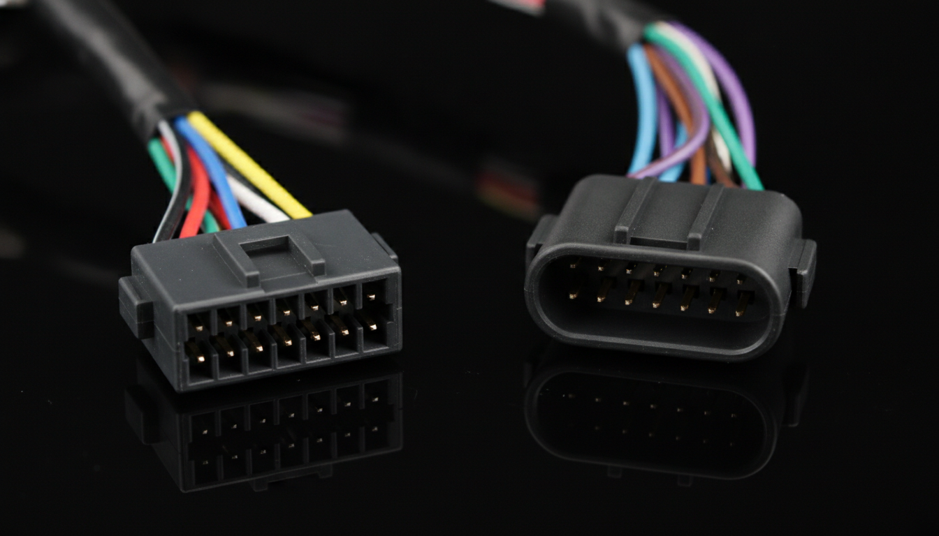
Alter Tag: Close-up of different Hyundai connector variations illustrating how generic charts fail to account for trim-level differences.
A pinout chart that does not originate from Hyundai's own documentation is built from reverse engineering or crowd-sourced data. That data often applies to a single trim or market and is recycled incorrectly across forums and download sites. The result is a diagram that shows 14 pins when your connector has 16, or assigns a signal wire to the pin that actually carries switched ground.
Hyundai produces hundreds of connector variations across its model range. The ix35 in Europe uses different audio harness connectors than the North American model, and even two ix35 vehicles with different trim levels will have different speaker connector pin assignments. This is exactly why one ix35 owner spent hours searching only to get the same incorrect image from every result.
The only fix is starting with a VIN-matched factory service manual. That manual's connector section ties every connector label to its harness position, pin count, pin function, and wire specification. No guesswork is involved when you have that data in front of you.
How Hyundai Numbers Wires and Pins in Schematics
Hyundai uses a consistent yet often misunderstood wire-coding system across all its service manuals. The number in a wire code represents the wire's cross-sectional diameter in millimeters. The letter or letter combination represents the insulation color. So "0.5G" means a 0.5mm wire with green insulation, and "1.25B/W" means a 1.25mm wire with black insulation and a white stripe.
Pin numbers on connector face views are always read from the locking tab side of the connector, not the wire entry side. This trips up many DIY mechanics who flip the connector over and count pins in the wrong direction. Counting from the wrong face reverses every pin assignment and sends every test to the wrong circuit.
Understanding Hyundai's factory wiring color codes and pin numbering direction is the first skill to lock in before touching any connector. Getting these two points right alone prevents most pinout errors on any Hyundai model.
Finding the Connector Index in Your Service Manual
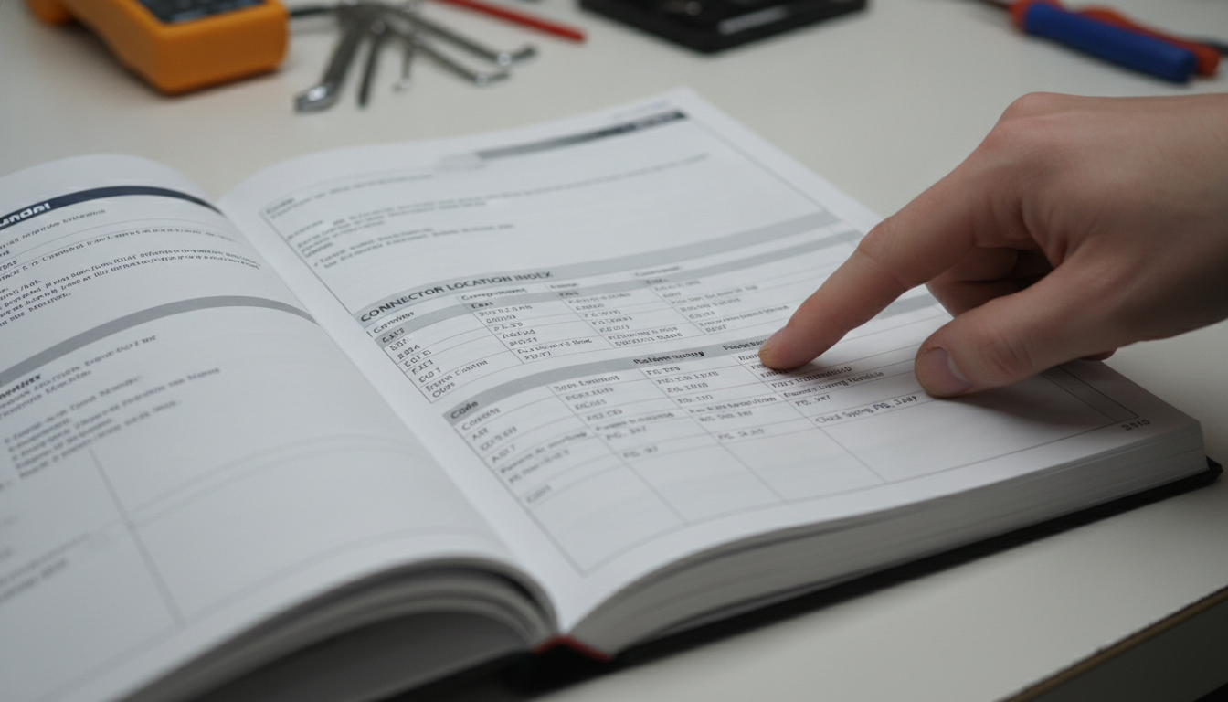
Alter Tag: Official Hyundai service manual showing the connector location index for engine and body harnesses.
Every Hyundai factory service manual contains a connector location index, usually at the start of the body electrical or wiring diagram section. This index lists every connector in the vehicle by its label code, its physical location in the car, and its diagram page reference.
Connector codes follow a pattern: a letter prefix identifies the harness (E for engine, B for body, C for chassis), and the number identifies the specific connector within that harness.
To find any pinout, start with the connector label code visible on the harness or in the wiring schematic. Take that code to the connector index. The index directs you to a connector face diagram showing exact pin positions, and then to the pin assignment table showing each pin's circuit function.
For Hyundai Europe models such as the Terracan or H-1 van, this process is identical, but the connector index is located in the body electrical section specific to that platform.
A complete Hyundai service manual sourced by VIN will include the connector index, the component location photos, and the full wiring diagrams in one place. Never try to use a manual from a different model year without confirming that the connector section applies to your specific build date.
ECU Connector Pinouts: What Each Pin Controls
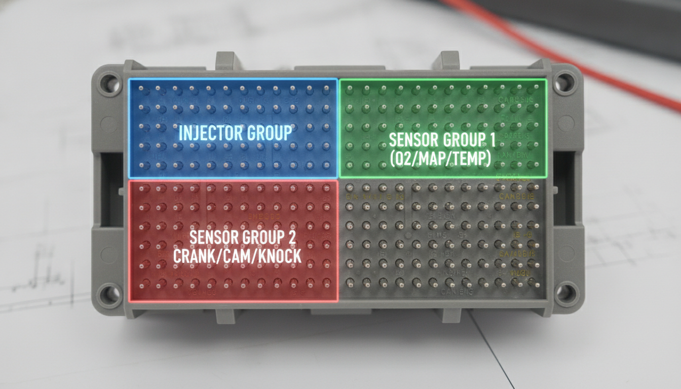
Alter Tag: Detailed view of a 121-pin Hyundai ECU connector block highlighting different circuit control groups.
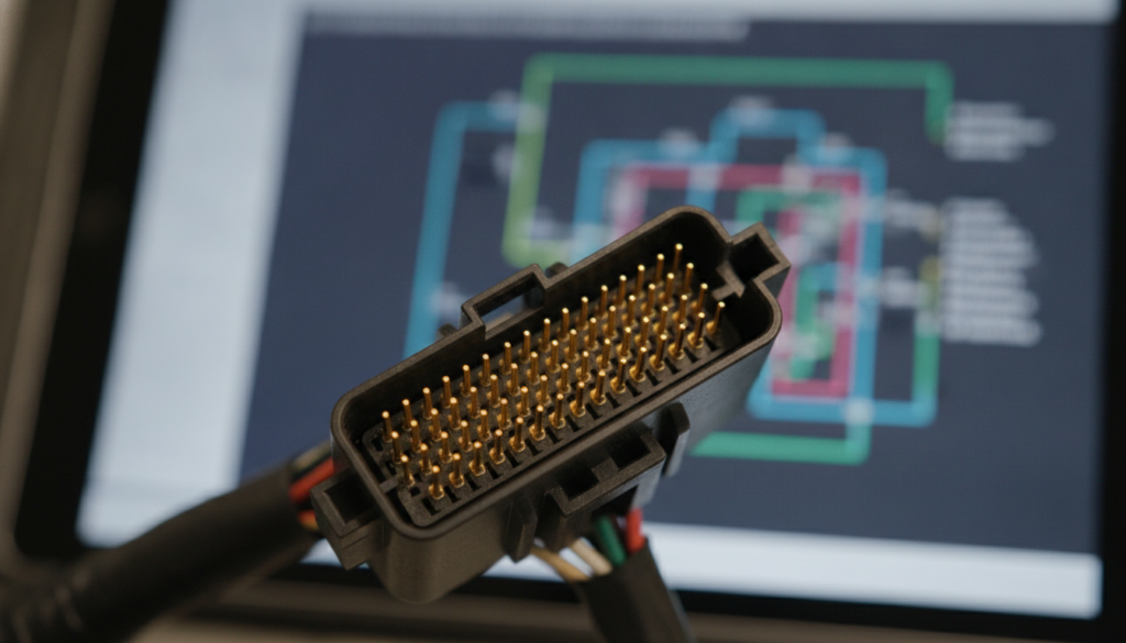
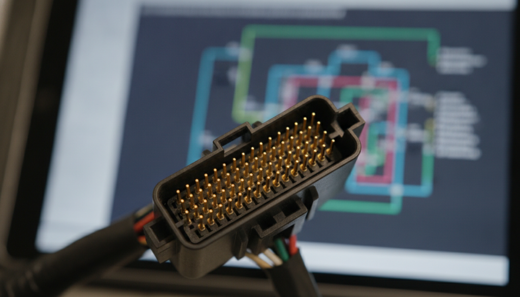
The engine control unit (ECU) on most Hyundai models uses a large multi-pin connector, often a 90-pin or 121-pin housing split across two or three connector blocks. Each block controls a specific group of circuits: injector drivers, sensor inputs, ignition outputs, ground references, and communication lines. Testing the wrong pin on an ECU connector during a live circuit test can inject voltage into a signal line, damaging the ECU.
Before probing any ECU connector pin, locate the ECU connector diagram in the engine management section of your Hyundai OEM workshop manual. The diagram will show which pins carry the crankshaft position sensor signal, which carry injector pulse width signals, and which are dedicated power and ground pins.
Cross-referencing DTC data with the ECU pinout lets you test only the flagged circuit, rather than sweeping across all pins in hopes of finding a fault. This is also covered in detail in the post on ECU pinout charts explained for diagnostics.
Male vs Female Locking Terminal Types
Hyundai ECU connectors use either single-locking or double-locking terminals, depending on the circuit's exposure to vibration. Single-locking terminals release with a flat-tip removal tool pressed against the locking arm.
Double-locking terminals have a secondary retainer that must be removed first before the primary locking arm can be depressed. Using the wrong removal method on a double-locking terminal cracks the housing and makes the connector unrepairable without a full harness splice.
The factory service manual specifies which terminal type is in each connector. Always confirm the locking type before attempting pin removal. A terminal removal tool kit matched to Hyundai terminal sizes prevents housing damage and keeps the connector reusable after testing.
Body Harness Connectors: Locating and Testing Safely
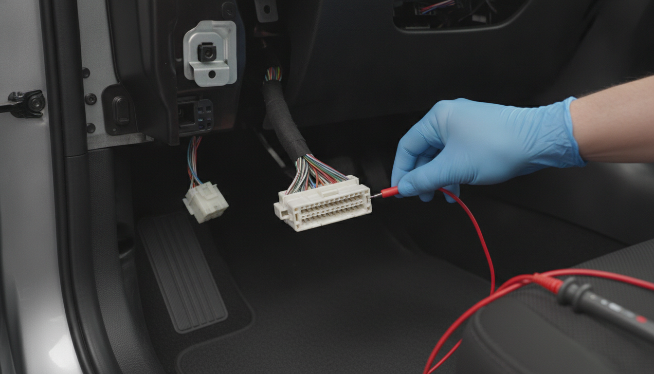
Alter Tag: Testing a Hyundai body harness connector located in the A-pillar with a professional back-probe method.
Body harness connectors cover a wide range of circuits including power windows, lighting, door locks, central locking, and HVAC. These connectors are physically large, often with 20 or more pins, and are distributed along the A-pillar, B-pillar, and under-dash harness runs.
Unlike engine harness connectors, body connectors are more likely to suffer corrosion from water ingress, especially at door and floor-level harness pass-throughs.
Before testing any body harness connector, disconnect the negative battery terminal and allow at least 2 minutes for capacitor discharge in any SRS-adjacent circuits. Relay testing procedures and manual pinouts often overlap with body harness connector data since relay base pins are drawn in the same harness section.
For models like the Hyundai Trajet or Santamo, which use older multi-pin body connector designs, the component location photos are critical because connectors are not always labeled on the harness itself.
Ground point locations on body harness connectors are found in the chassis ground diagram subsection.
This maps every chassis ground bolt location and confirms which connector pins tie to each ground point. Poor ground pin connections at body harness connectors are a leading cause of intermittent electrical faults on higher-mileage Hyundai vehicles.
Sensor Connector Pinouts: Cam, Crank, O2, and MAF
Engine sensor connectors on Hyundai models typically range from 2-pin to 4-pin and follow predictable patterns across engine families. Crankshaft and camshaft position sensors on most Hyundai four-cylinder engines use a 3-pin connector: pin 1 is the power supply (5V reference), pin 2 is the signal output, and pin 3 is the sensor ground.
However, the physical pin numbering direction must be confirmed on the connector face diagram in your specific manual, as the connector housing orientation varies by engine bay packaging.
MAF (mass airflow) sensors on Hyundai models typically use a 4-pin or 5-pin connector. The additional pins carry an intake air temperature signal alongside the MAF signal. Oxygen sensors use a 4-wire connector on most heated units: two heater-circuit wires and two signal-circuit wires.
Testing any of these connectors with a multimeter requires knowing which pin carries which signal, and that information comes directly from the sensor connector pinout table in the engine management section of the Hyundai workshop documentation.
For older European models like the Hyundai Lantra, Galloper, or S-Coupe, the sensor connector pinouts are found in the engine electrical section of the respective platform manual.
These older connectors often have different pin counts than those of later models due to simpler engine management systems. Always confirm the platform year before assuming pin function.
Audio and Accessory Harness Pinout Lookup Process
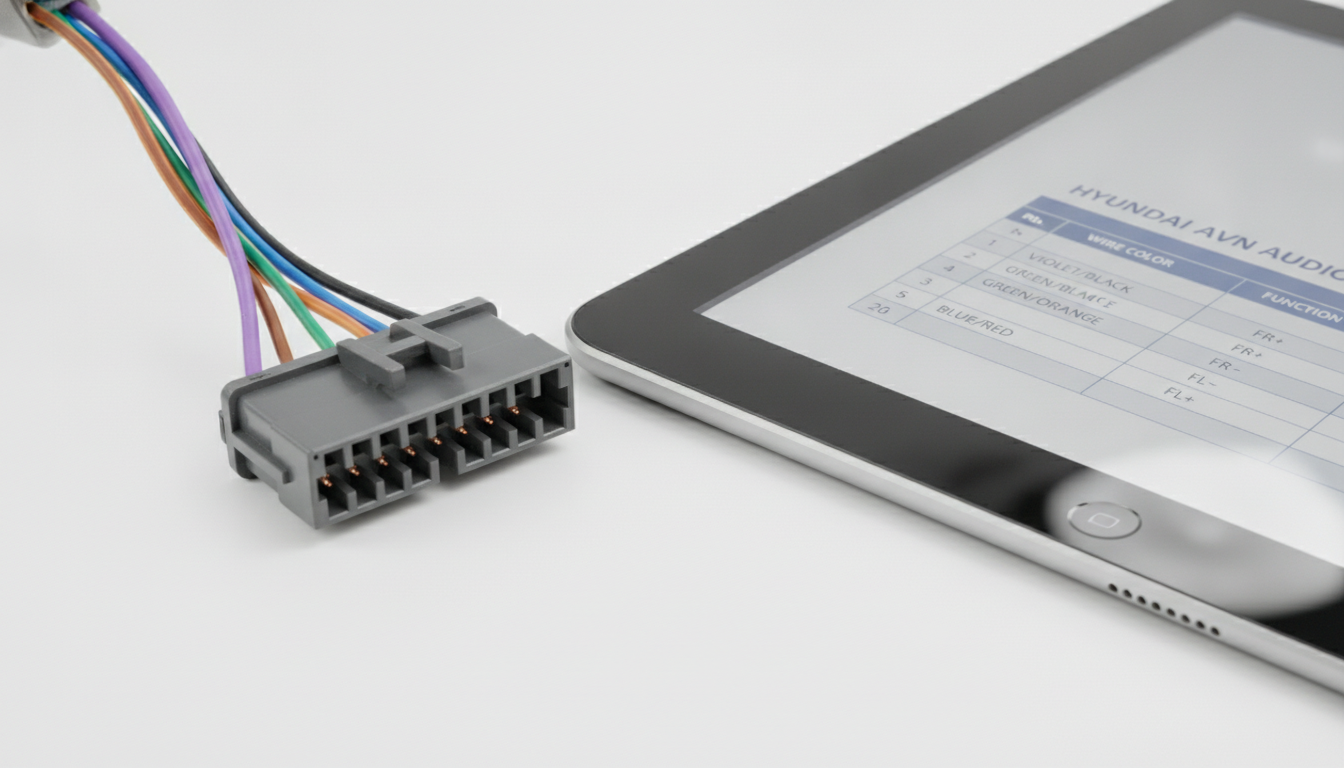
Alter Tag: Hyundai 26-pin audio head unit connector and pinout table for speaker circuit routing.
Audio harness connector pinouts are among the most-searched Hyundai wiring topics because aftermarket head unit installs require knowing the function of every pin before splicing.
Hyundai radio connectors changed across generations and market variants, and even two vehicles with the same model name but different trim levels may use different connector housings. A 14-pin connector on a base-trim model may be a 20-pin or 26-pin unit on a navigation-equipped variant.
The correct lookup path starts with the AVN (Audio-Visual-Navigation) system section in the body electrical chapter of the factory service manual. That section contains the head unit connector face diagram, the full pin assignment table for each connector block, and the speaker circuit routing.
For models like the Hyundai Getz or Atos, the audio section is compact, but the same lookup process applies. For the Grand Santa Fe with amplifier and rear camera, the audio connector section spans multiple subsystems and requires cross-referencing the amplifier sub-harness pins separately from the head unit connector.
Wire color codes in the audio section follow the same number-and-letter format used throughout the Hyundai wiring manual. Speaker wires are typically identified by a base color with a stripe, such as "0.5V/B," which is violet with a black stripe.
Confirming the wire color against the pinout table before splicing removes the need to guess which wire carries which channel.
Terminal Testing: Tension, Resistance, and Voltage Checks
After identifying the correct pin using your factory pinout data, the next step is testing the terminal itself before probing its circuit. Hyundai factory procedures specify the use of a terminal tension gauge to confirm that the female terminal's contact spring still grips a mating male pin with enough force.
A female terminal with weak spring tension will read correct voltage during a static test but drop voltage or lose contact during vibration, creating intermittent fault codes that are nearly impossible to diagnose without this check.
For resistance and voltage tests, always use the back-probe method with a thin-tip adapter rather than inserting a probe tip directly into the connector face. Back-probing through the wire seal preserves the terminal's contact surface.
Direct face-probing with a standard multimeter tip spreads the female terminal opening and permanently reduces spring tension. The multimeter sensor testing procedures in OEM manuals cover the correct back-probe technique and expected reference voltage ranges for each sensor type.
For voltage drop testing on power supply pins, the alternator voltage drop testing steps post provides additional context on acceptable drop limits at harness connectors.
Common Pinout Errors That Damage Hyundai Terminals
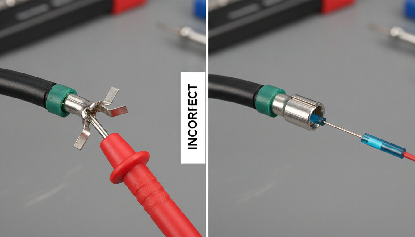
Alter Tag: Comparison of damaging direct-face probing vs safe back-probing on a Hyundai connector terminal.
The most damaging pinout error is confirming the wrong connector face orientation and probing pin 1 when the actual target is pin 10. On a 10-pin connector, these two pins are at opposite ends, and on an ECU connector, this mistake can inject battery voltage into a low-current signal circuit.
A blown ECU output driver is not covered under any warranty if caused by incorrect probing during a DIY test.
The second most common error is using a generic pinout from a different market variant. For example, the Hyundai Tucson sold in North America has different sensor connector pinouts than the Tucson sold in Europe under some production year ranges.
The same is true for models like the Hyundai Santa Fe and Sonata, both of which have market-specific wiring differences in engine and body circuits. Using a VIN-matched factory manual eliminates this risk entirely by supplying only the data for your exact vehicle.
The third error is failing to verify the connector housing retention type before attempting pin removal. Forcing a single-locking removal tool into a double-locking connector cracks the secondary retainer. The repair then requires splicing in a new connector housing, which is an avoidable cost.
The factory manual lists the terminal type for every connector in the vehicle. Checking this detail before starting saves both money and repair time. For models with complex multi-locking connectors, such as the Hyundai Veloster and Genesis, the manual's wiring repair section includes step-by-step photos of the correct tool application technique.
Similar care applies to the ix20 and ix55, where body-harness connectors use mixed locking types within the same harness run. The Matrix and i30CW use similar wiring structures, so consulting the connector index for each before starting any repair remains essential.
Common Asked Questions Hyundai Connector Pinout
Where is the connector location index in a Hyundai factory service manual?
The connector location index is located at the start of the wiring diagram or the body electrical section in the Hyundai factory service manual. It lists every connector in the vehicle by its harness code label (e.g., E for engine harness or B for body harness), along with its physical location and the page reference for the connector face diagram and pin assignment table.
Some manual editions place the index at the beginning of each chapter rather than in one central location. Always check both the wiring diagram chapter index and the specific system chapter index for the circuit you are working on.
What do the numbers and letters mean on Hyundai wiring diagrams?
Hyundai wiring diagrams use a two-part wire code. The number at the start of the code represents the wire's cross-sectional diameter in millimeters, so "0.5" means a 0.5mm wire. The letter or letters that follow indicate the insulation color.
A single letter, such as "G," indicates solid green. Two letters separated by a slash, such as "B/W," mean the base color is black with a white stripe.
This coding system is consistent across Hyundai's entire model range and is explained in the wiring diagram introduction section of any factory service manual. Matching this code to the pinout table confirms both the circuit function and the physical wire to test.
Can I use a Hyundai wiring diagram from a different model year for pinout data?
Using a wiring diagram from a different model year is a significant risk, especially for ECU connectors and body electronics. Hyundai revised connector designs, pin counts, and wire routing across production runs, and in some cases, mid-year production changes affect connector pinouts without a model year change.
The safest approach is always to use a factory service manual matched to your exact VIN. The VIN encodes the production year, engine variant, and market region, and a VIN-matched manual will include only the connector data that applies to your specific vehicle build.
How do I avoid damaging Hyundai ECU connector terminals during testing?
Avoiding terminal damage during ECU connector testing comes down to three steps. First, always confirm the correct pin number and function from the factory pinout table before touching the connector. Second, use the back-probe method with a fine-tip adapter rather than inserting a probe directly into the connector face, which can spread and weaken the female terminal's contact spring.
Third, check whether the connector uses single- or double-locking terminals before removing any pin, as forcing the wrong release tool can crack the housing. Factory service manuals include terminal repair kit part numbers and the correct removal tool type for every ECU connector in the vehicle.
Why does my Hyundai audio connector pinout not match any diagram I find online?
Hyundai audio connector pinouts vary by model, production year, market region, and trim level. A base-trim model may use a 14-pin radio connector, while an identical model year with navigation uses a 20-pin or 26-pin unit.
Online diagrams are frequently mislabeled, region-specific, or based on a different trim than the one being installed.
The only reliable source is the AVN system section of your vehicle's factory service manual, which contains the head unit connector face diagram and full pin assignment table matched to your exact trim specification.
If your manual does not include the AVN section, Hyundai sometimes issues a separate supplement manual for the audio system.