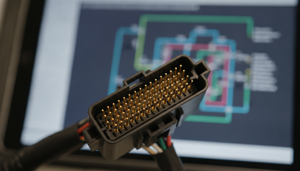
An incorrect ECM pin test can quickly create a bigger problem. One slipped probe can damage a terminal or confuse your diagnosis. Hyundai engine faults need a diagram, not guesswork.
Prioritize power, ground, connector views, and relay logic over trouble codes. Use a meter to trace circuits according to the standardized architecture of Hyundai Engine Control Module (ECM) diagrams, which link power, sensors, and actuators. Accurate schematics for your specific year, model, and engine are vital, as pinouts vary by powertrain design.
This guide shows how to read the diagram with a clear path. You’ll learn what to test first and what to ignore. You’ll also see how to match the right manual before touching the ECM.
Hyundai ECM Wiring Diagram Guide: The safer way to trace engine control faults
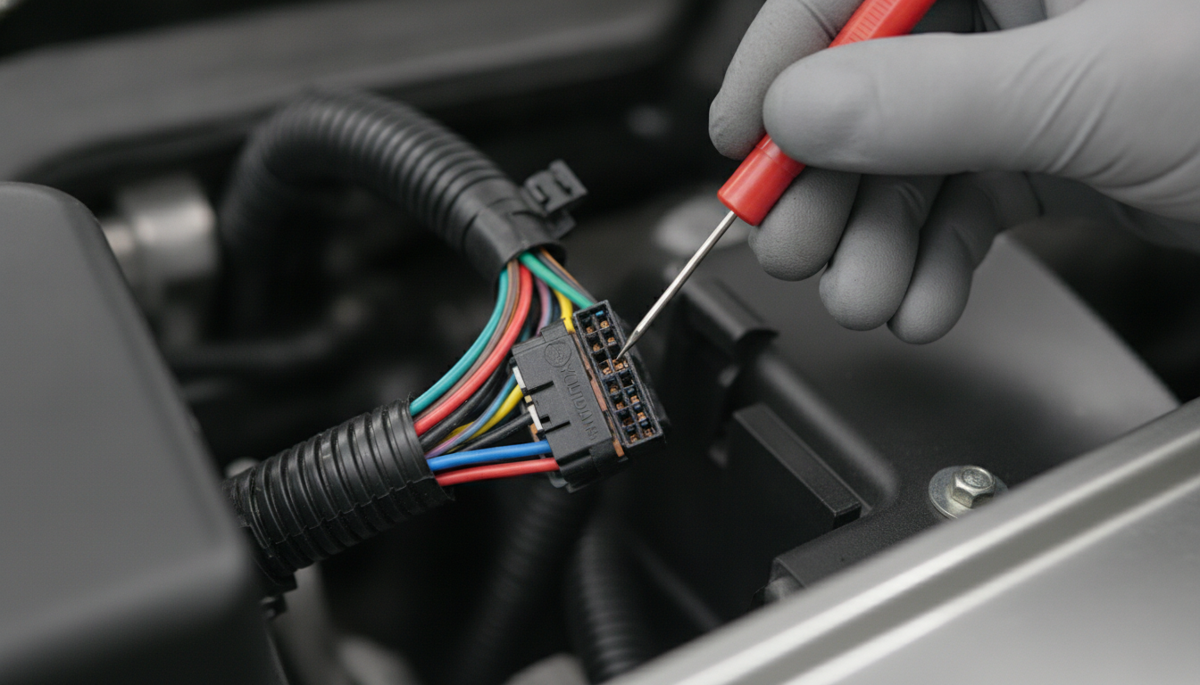
Alter Tag: Technician safely back-probing a Hyundai ECM connector pin to trace engine control circuit faults.
A Hyundai ECM wiring diagram should answer one practical question. It should show where the ECM receives power, where it grounds, and how it talks to sensors, relays, injectors, coils, and the scan tool. The right diagram turns a no-start mystery into a controlled test sequence.
Match the exact Hyundai diagram first
A Hyundai ECM diagram only helps when it matches the exact vehicle. Year, engine code, market, transmission, and emissions package can change connector layouts. A close diagram can still send you to the wrong pin.
Start with the manual source before you start probing. NXT Motors keeps Hyundai coverage organized through the Hyundai repair manual hub, so you can narrow the search by model instead of grabbing a random image. That matters because ECM connector pins may differ between engines that look similar.
Use model pages when the symptom points to a specific vehicle. You can check an Atos ECM diagram set, an Azera ECU connector guide, or a Santa Fe ECM schematic before testing anything. You can also compare a Sonata ECU wiring path, a Tucson engine harness diagram, and a Veloster ECM test page when the fault is common to a shared engine family.
Older and regional models need the same care. Use the Excel sensor circuit guide, Getz ECU pin reference, i10 ECM connector map, and i20 engine wiring manual when the vehicle belongs to those lines. For larger platforms, verify with the Genesis powertrain wiring source, the Equus ECM wiring notes, the Centennial control module manual, the Veracruz powertrain diagram, and the XG 350 ECU circuit file.
European Hyundai pages help when the badge, engine, or market name differs. Check the Accent X3 harness layout, Galloper electrical manual, Grand Santa Fe control diagrams, and H-1 engine wiring file for regional coverage. Also match niche models through the Trajet ECM signal chart, Terracan ECU testing pages, Santamo wiring reference, and S-Coupe sensor schematic.
Do not skip older compact pages. A Pony factory wiring set, Matrix ECM circuit manual, Lantra control harness guide, ix55 module wiring notes, ix35 ECU connector data, ix20 engine control diagram, and i30cw wiring diagnostic file can prevent a wrong connector callout. That one step protects both the ECM and the harness.
Decode the ECM connector view
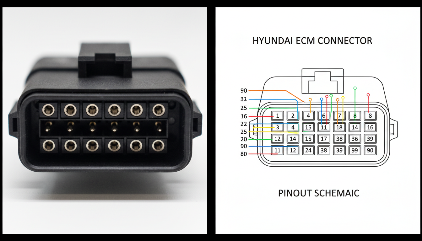
Alter Tag: Detailed comparison between a physical Hyundai ECM connector and its corresponding technical pinout diagram.
The connector view is where many mistakes begin. A diagram may show the terminal side, harness side, or component side. If you read it backward, every pin test becomes suspect.
Before back-probing, find the connector name and pin numbering rule. Look for cavity numbers, locking tab position, connector face direction, and wire colors. Then compare the drawing to the real connector before connecting a meter.
Use ECM pinout pages to group the circuit before testing. Battery feeds, ignition feeds, grounds, 5V references, sensor returns, communication lines, injector drivers, and coil drivers should not be treated the same. A pinout tells you what kind of signal should exist at that cavity.
This is where related NXT Motors guides fit naturally. Refer to the ECU pinout chart when the connector table is confusing. Use factory wire color decoding when the diagram gives wire colors that do not look obvious at the harness.
Prove power and ground first
Do not replace an ECM until it has clean power and ground. A dead module, a missing Check Engine light, no communication, or no fuel pump command can all stem from a feed issue. The wiring diagram tells you where to prove it.
Start with the battery feed pins. These should usually have voltage when the circuit design calls for constant supply. Then test ignition feed pins with the key in the correct position.
Ground testing needs more than continuity. A wire can show continuity and still fail under load. Use voltage drop testing while the circuit is active, because resistance only becomes obvious when current flows.
The Hyundai wiring manual catalog is useful here because it often includes sections on fuses, relays, grounds, connectors, and harnesses. Pair that with a relay pinout test routine when the ECM relay does not behave as expected. Use hidden chassis ground lookup when a shared ground point feeds more than one symptom.
Trace shared sensor circuits
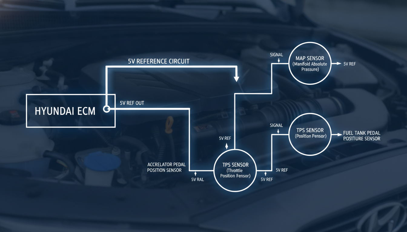
Alter Tag: Wiring diagram showing shared 5V reference circuits between various Hyundai engine sensors and the ECM.
Sensor codes can be misleading when several sensors share a single feed. A shorted sensor wire can pull down a reference circuit and make unrelated sensors look bad. The wiring diagram shows which components share that branch.
Look for 5V reference, sensor ground, and signal return lines. Then unplug the sensors on that branch, one at a time, while monitoring the voltage. If the reference comes back after one sensor disconnects, you have found the loaded section.
Do not jump from a code to a part. A throttle, MAP, cam, crank, pressure, or temperature code may indicate a circuit condition rather than a failed sensor. The diagram lets you separate the sensor, connector, harness, and ECM driver.
Use sensor multimeter checks to confirm what the meter should show. Use short-tracing wiring method when a reference circuit falls to zero. Use OBD-II flowchart checks when codes need a factory test order.
Follow relays before blaming modules
A clicking relay does not prove the ECM works. It only proves some part of the control path has activity. You still need the diagram to see coil power, coil ground, switched feed, and load output.
Hyundai circuits may use ground-side control in some designs. That means the relay can receive power and wait for the ECM or control path to provide ground. Testing only one relay terminal can lead to the wrong conclusion.
Use the schematic to mark four points. Find the relay battery supply, relay coil supply, relay control side, and output to the ECM or load. Then test each point under the exact key state shown in the manual.
A relay fault can also be a fuse, ignition switch, corroded connector, or broken harness feed. The diagram keeps those possibilities in order. That order saves money because it tests the path before the expensive module.
Decide before replacing the ECM
Alter Tag: Final verification checklist being performed before proceeding with a Hyundai ECM module replacement.
An ECM should be the last suspect, not the first purchase. It needs confirmed battery feed, ignition feed, ground integrity, communication wiring, and sensor reference behavior. Without those checks, replacement becomes a gamble.
Use the Hyundai diagnostic manual source when the symptom involves no communication, no start, limp mode, repeated fuse failures, or multiple sensor codes. The correct manual gives you the pinout and the surrounding system view. That is the difference between testing one pin and understanding the circuit.
Before buying a module, record the voltage values. Note the connector name, pin number, wire color, key position, and reading. Then compare those notes against the diagram.
If the ECM has correct feeds, clean grounds, stable references, intact communication wiring, and still fails the factory decision point, replacement becomes more reasonable. Until then, the diagram is your best protection. It keeps the diagnosis evidence-based and prevents parts-guessing.
Common Asked Questions About the Hyundai ECM Wiring Diagram Guide
How do I know if a Hyundai ECM wiring diagram matches my car?
Check the year, model, engine size, engine code, transmission, and market before trusting the diagram. Hyundai models can share names while using different connectors, emissions layouts, or control strategies.
Compare the ECM connector shape, locking tab, cavity count, pin numbers, and wire colors against the vehicle before testing. If the connector view does not match the car, stop and find the correct manual.
An incorrect diagram can lead you to probe a driver circuit as if it were at ground. That can damage terminals or create false readings. Use the manual section that includes the schematic, connector view, component location, and harness layout.
Can a bad ECM cause no communication with a scan tool?
Yes, but a bad ECM is not the first thing to assume. No communication can come from missing ECM power, weak ground, blown fuse, failed relay output, damaged communication wiring, or a dead diagnostic connector feed.
Start by checking the DLC power and ground, then verify the ECM battery and ignition feeds. Next, voltage-drop the ECM grounds under load. If those pass, inspect communication lines for shorts, opens, or damaged connectors.
Only after the circuit tests match the manual should the ECM move higher on the suspect list. This order prevents the replacement of a module that never received proper voltage.
Why do several Hyundai sensor codes appear together?
Several sensor codes can appear together when they share a 5V reference or sensor ground. One shorted sensor, a rubbed wire, a wet connector, or a crushed section of the harness can pull down the shared circuit.
The ECM then detects several abnormal signals simultaneously and stores codes for different components. Open the diagram and identify every sensor on the same reference branch. Measure the reference voltage, then unplug related sensors one at a time while watching the reading.
If voltage returns after one connector is unplugged, inspect that sensor and its wiring. This method is faster than replacing every sensor named by the scan tool.
Should I test the ECM fuse or the ECM connector first?
Start with the fuse only as a quick check, then confirm voltage at the ECM connector. A fuse can test good while the circuit still loses voltage through a relay, connector, splice, or damaged wire. The ECM connector test proves what the module actually receives.
Use the wiring diagram to identify constant battery feed, ignition feed, and relay-fed pins. Test them in the key position specified by the manual.
Then check voltage drop on ECM grounds while the circuit is loaded. This sequence gives a real answer. It also prevents assuming a good fuse means a healthy ECM supply path.
Are free Hyundai ECM wiring diagrams safe to use?
Free diagrams can help with orientation, but they are risky when they lack model, year, engine, connector view, and revision details. Many shared diagrams are cropped, mislabeled, or taken from a different market version.
That matters because ECM connectors can have many pins with similar wire colors and different functions. Use free information only to understand the circuit's general idea.
For actual testing, use a manual that includes a schematic, connector configuration, component location, fuse data, relay path, and harness layout. The safest rule is simple. Never back-probe an ECM pin unless the connector view and wire color match the vehicle in front of you.