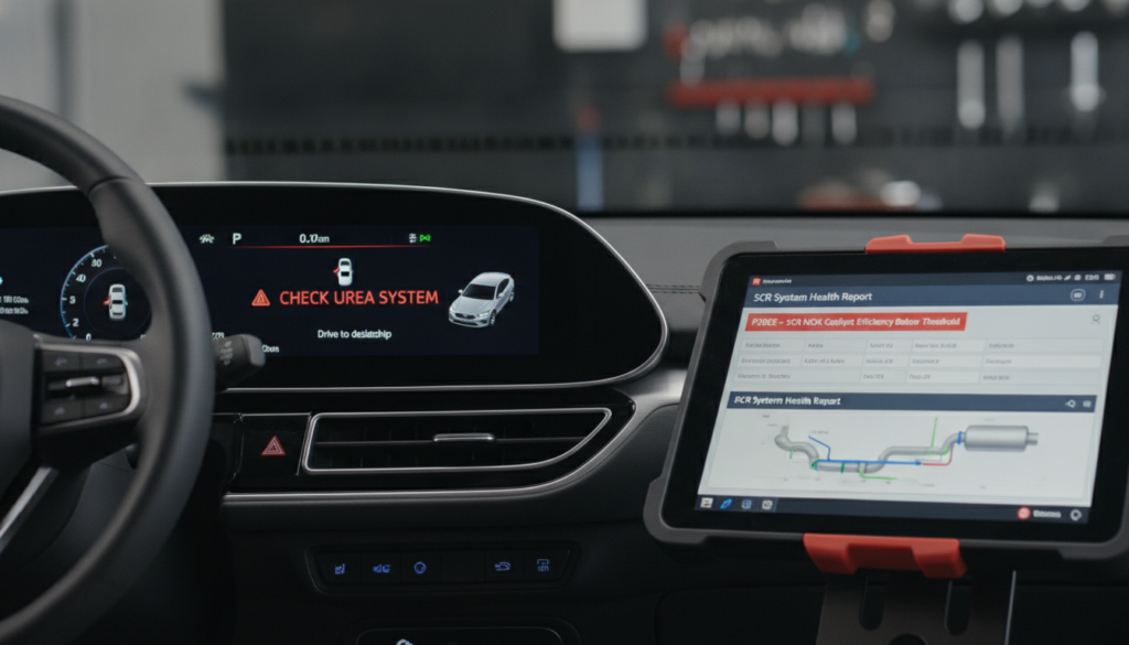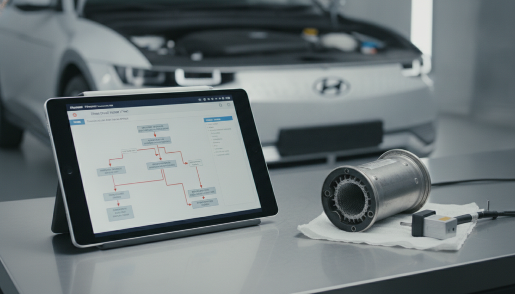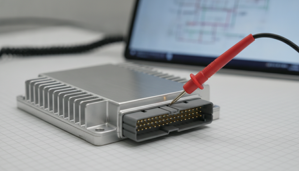
A Hyundai that cranks but won’t start can get expensive fast. The ECU may appear to be at fault when the real fault lies in a feed wire, ground, relay, connector, or shared sensor circuit. Random parts replacement can turn one wiring fault into several new problems.
Effective diagnosis requires testing power, ground, and communication lines using a factory diagram and multimeter. Indicators such as OBD2 failure or blown fuses signal wiring issues. Always disconnect the negative battery terminal before testing.
This guide shows a practical Hyundai ECU wiring troubleshooting path. You’ll learn how to read the right pinout, test circuits under load, and decide when the ECU is actually suspect. The goal is a confident repair decision before money goes into modules.
Hyundai ECU wiring troubleshooting: The 7-check path that stops wrong ECU replacement
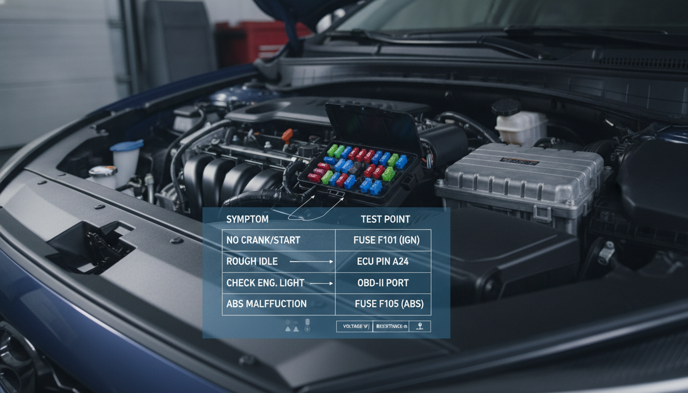
Alter Tag: Infographic showing the 7-check path for Hyundai ECU wiring troubleshooting and circuit diagnosis.
Hyundai ECU wiring troubleshooting works best when you treat the ECU as part of a circuit rather than a mystery box. The correct path starts with the exact model wiring diagram, then moves through power feeds, grounds, reference voltage, CAN communication, and connector condition. That order keeps you from condemning a module that never received clean voltage.
Confirm the symptom before chasing pins
Start by separating no-crank, crank-no-start, no-communication, and intermittent-running problems. Each symptom points to a different part of the Hyundai ECU wiring diagram. A clear symptom saves hours before the first back-probe.
A no-crank fault can involve the starter relay, park switch, clutch switch, immobilizer, ignition switch, or ECU relay command. A crank-no-start fault usually requires checks of the RPM signal, injector pulse, ignition command, fuel pump control, and ECU wake-up. A no-communication fault starts at OBD power, grounds, CAN wiring, and ECM voltage feeds.
Write down what the car does with the key on, while cranking, and after the fault appears. Note the check engine light behavior, scan tool access, relay clicks, fuel pump priming, and warning lights. Those details tell you which diagram page to look at first.
Use a Hyundai-specific manual instead of a generic chart when the car has multiple engine, market, or production variants. The Hyundai factory manual hub is the first place to narrow the diagnostic path by brand and model. A correct manual turns vague symptoms into exact locations for connectors, fuses, splices, and grounds.
Do not unplug the ECU first unless the test requires it. Many faults only show under load with the connector attached. Back-probing with proper pins protects the connector and keeps the circuit operating during measurement.
Match the diagram to the exact Hyundai
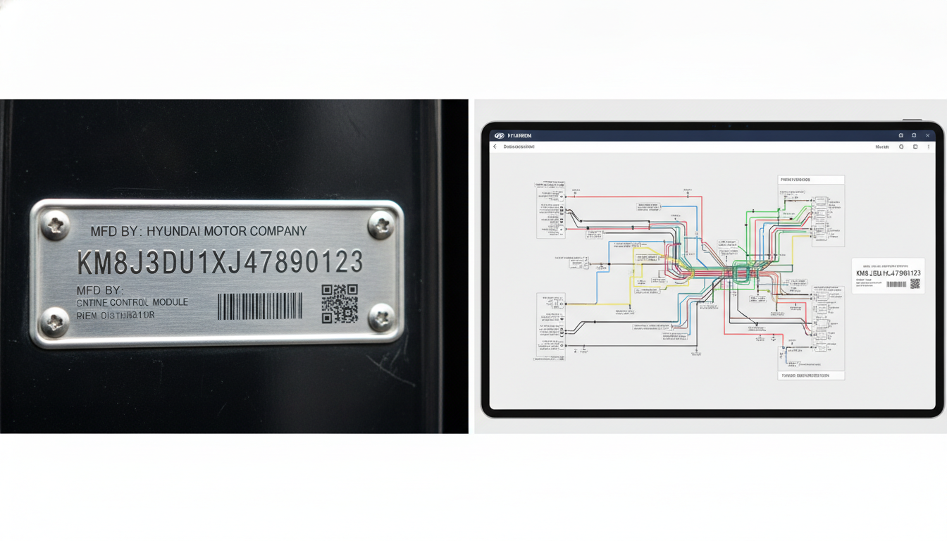
Alter Tag: Matching a Hyundai VIN to a specific factory wiring diagram for accurate ECU pinout identification.
A Hyundai ECU pinout is only useful when it matches the engine, year, market, transmission, and connector style. A close diagram can mislead you when one pin changes function. That mistake can make a good ECU look dead.
Confirm the VIN, engine code, production date, and trim before testing. Then match the connector face, cavity count, wire color, and component location page. The connector view matters because front-view and harness-side diagrams can reverse pin positions.
Use model pages when the manual must match the vehicle. For older city cars, check the Hyundai Atos repair manual or Hyundai Getz service guide before testing small-engine ECU feeds. For compact models, use the Hyundai i10 manual page, the Hyundai i20 wiring resource, or the Hyundai Accent X3 manual when the connector layout varies by region.
Mid-size and performance models need the same care. Use the Hyundai Sonata workshop manual, Hyundai Tiburon repair data, Hyundai Coupe wiring guide, Hyundai Veloster service manual, or Hyundai S-Coupe electrical manual when testing engine-control circuits. These pages help keep the diagnostic path tied to the vehicle rather than to a random online pinout.
A factory schematic also shows splice points, grounds, connector IDs, and harness routes. That information matters when two dead ECU pins share one upstream feed. Without that map, you may test the same failed branch several times.
Prove ECU power before blaming modules
The ECU cannot communicate, command relays, or control injectors without the correct power feeds. Some feeds are at a constant battery voltage, while others appear only with the ignition on or during startup. Testing only one feed can miss the circuit that wakes the module.
Start at the fuse and relay shown in the manual, then move toward the ECU connector. Check the battery voltage, ignition voltage, and relay output voltage at the correct pins. Use the Hyundai workshop manual library when you need the exact ECM fuse, main relay, and pin location.
A digital multimeter can show voltage on a weak circuit that fails under load. Load the circuit with a safe test light or approved load tool when the manual allows it. A corroded fuse contact may show 12 volts unloaded but collapse when the ECU needs current.
Large sedans and luxury models can have more module feeds than expected. Use the Hyundai Azera ECM manual, Hyundai Genesis diagnostic manual, Hyundai Equus electrical guide, Hyundai Centennial service data, and Hyundai XG 350 repair manual for model-specific power distribution. These models often make generic diagrams risky.
If power is missing at the ECU, do not jump power into the pin unless you fully understand the circuit. A fused jumper used incorrectly can backfeed another module. Trace the source through the fuse, relay, splice, connector, and harness route.
Load-test grounds before reading sensors
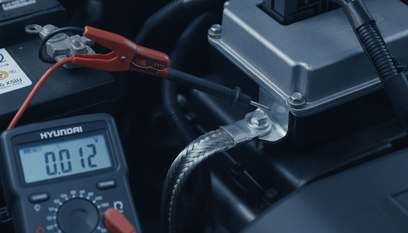
Alter Tag: Performing a voltage drop test on a Hyundai ECU ground circuit to verify electrical return path.
Faulty ECU grounds can cause sensor codes, no-start faults, loss of communication, and strange warning lights. A ground can pass a simple continuity test and still fail under operating load. That is why voltage drop matters more than resistance alone.
Test each ECU ground with the circuit active. Place one meter lead on the ECU ground pin and the other on the battery negative terminal. A high reading during cranking or key-on load indicates resistance in the ECU-to-battery return path.
Ground faults can also distort a 5V reference circuit. A sensor may look shorted when the actual return path is weak. The hidden chassis ground point guide helps readers understand why factory ground locations matter during electrical diagnosis.
SUV and van models require careful ground-location checks because the harness routing is longer. Use the Hyundai Santa Fe manual page, Hyundai Tucson wiring manual, Hyundai Veracruz service guide, Hyundai Grand Santa Fe manual, and Hyundai ix55 repair manual to locate exact ground points. These pages help avoid guessing under the dash or behind the engine.
Clean the ground only after you prove the drop. Then retest the same pin under the same load. A repair is not finished until the voltage drop improves and the symptom changes.
Isolate 5V reference faults fast
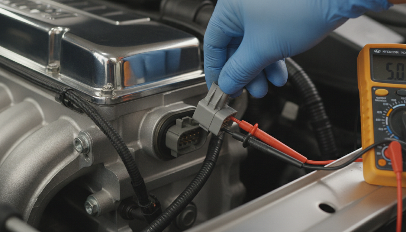
Alter Tag: Testing the 5V reference circuit on a Hyundai sensor harness to isolate shorted components.
A failed 5V reference line can create several sensor codes at once. It can also keep the ECU from waking a relay or reporting normal scan data. The trick is to find whether the short sits in a sensor, wire, connector, or ECU output.
Start by identifying every sensor on the shared 5V circuit. The manual may group throttle position, accelerator pedal, manifold pressure, crank, cam, or pressure sensors into a single reference branch. One shorted sensor can pull the entire branch low.
Measure the 5V reference at the ECU pin and at the easiest sensor connector. If voltage is low, unplug sensors on that branch one at a time. When the 5V returns, inspect that sensor and its connector before blaming the ECU.
The multimeter sensor testing guide pairs well with this step, as sensor voltage checks require context. The ECU pinout chart guide also helps explain why a single pin can power multiple components. Use those references before replacing an ECU for a shared sensor fault.
Older Hyundai models can have brittle connectors and previous repair splices. Use the Hyundai Excel workshop manual, Hyundai Pony electrical manual, Hyundai Lantra repair guide, and Hyundai Matrix service manual when testing older harness sections. The right connector view reduces the risk of spreading terminals.
Verify CAN wires before replacing ECUs
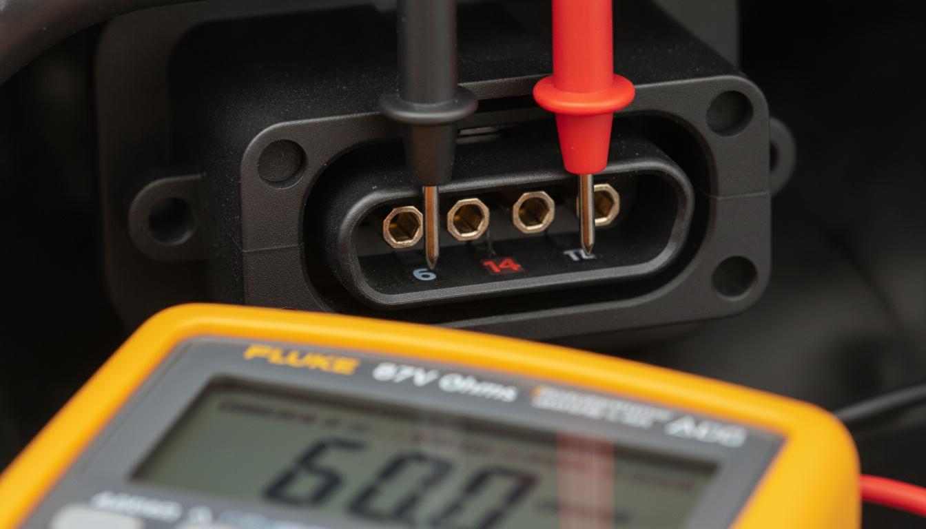
Alter Tag: Measuring CAN High and CAN Low resistance at the Hyundai OBD-II port to check network integrity.
No communication does not automatically mean the Hyundai ECU has failed. The scan tool talks through the OBD port, network wiring, and module power circuits. A fault anywhere in that chain can appear to be a dead ECU.
Start with the OBD connector. Confirm power and ground at the diagnostic port before chasing the ECU. Then test CAN High and CAN Low according to the wiring diagram and the vehicle network layout.
With the battery disconnected and modules asleep, many CAN systems show about 60 ohms across the correct CAN pair. A reading near 120 ohms can indicate a missing termination path. A very low reading can suggest a shorted wire or module pulling the network down.
The read-only wiring diagram guide helps readers trace network faults without cutting open the wrong harness. The OBD-II code flowchart guide also fits when communication returns and stored codes need sorting. CAN checks should happen before buying a programmed ECU.
Regional Hyundai models may use different network layouts and connector locations. Use the Hyundai ix35 wiring manual, Hyundai ix20 repair manual, Hyundai i30cw service data, Hyundai H-1 workshop guide, and Hyundai Trajet electrical guide before testing network pins. The exact diagram prevents a false CAN diagnosis.
Inspect connectors where failures hide
ECU wiring faults often hide at connectors, not in the middle of the harness. Water, battery acid, heat, vibration, rodent damage, and previous probing can damage terminals. A pin that looks connected can open when the harness moves.
Inspect the ECU connector with the battery disconnected. Look for green corrosion, pushed-back terminals, loose locks, bent pins, swelling seals, and moisture tracks. Then compare the connector face with the factory connector configuration.
Perform a gentle pin-drag test only with the correct test terminal. Do not force a meter probe into a small female terminal. Spread terminals create intermittent faults that appear after the car leaves the workshop.
Some body styles place harnesses where water and vibration create repeat failures. Use the Hyundai Galloper repair manual, Hyundai Terracan wiring guide, Hyundai Santamo manual page, and Hyundai i30cw harness resource to locate connectors across larger bodies. The connector layout can save more time than the schematic alone.
Wire colors also matter after previous repairs. The factory wiring color code guide helps decode color abbreviations before splicing. A correct repair should match gauge, insulation, routing, and seal quality.
Choose repair, manual, or ECU replacement
Alter Tag: Final verification of Hyundai ECU replacement following a complete wiring troubleshooting path.
Replace the ECU only after the power, ground, 5V reference, communication, connectors, and related relays have passed testing. A failed module is possible, but it should be the last confirmed result. The evidence should show that the ECU receives correct inputs and still fails to respond or command outputs.
Create a final decision sheet before buying parts. Record battery voltage, ignition feed voltage, loaded ground drop, 5V reference value, CAN resistance, connector condition, and scan-tool behavior. That sheet protects you from repeating the same tests after a replacement ECU arrives.
The Hyundai model repair manual index should serve as the reference point for readers who need exact diagrams. A factory manual is most useful when the fault involves multiple pins, hidden grounds, splice packs, or model-specific connector views. It helps owners and workshops avoid the cost of wrong modules.
Use related guides when the fault overlaps with another circuit. The relay testing procedure guide helps when the ECU depends on a main relay. The parasitic drain schematic guide helps when ECU wake-up issues drain the battery.
The best repair path is simple but disciplined. Confirm the diagram, test the live circuit, repair the proven fault, and retest the original symptom. That is how Hyundai ECU wiring troubleshooting stops guesswork and turns a confusing electrical fault into a controlled diagnostic decision.
Common Asked Questions About Hyundai ECU Wiring Troubleshooting
Can a Hyundai ECU wiring fault cause a no-start without any codes?
Yes, a Hyundai ECU wiring fault can cause a no-start condition without useful codes. If the ECU loses power, ground, relay feed, crank signal, or communication, it may not stay awake long enough to store faults.
A scanner may also fail to access the ECM when the network, OBD port, or ECU feed is compromised. Start by confirming check engine light behavior with the key on, then test ECM power and grounds at the connector.
After that, check the crank signal, the main relay output, and the 5V reference. Codes help when available, but wiring proof matters more when the ECU cannot communicate.
Why does my scan tool power up but not talk to the Hyundai ECM?
A scan tool can power up from the OBD port and still fail to communicate with the Hyundai ECM. Pin power at the diagnostic connector only proves the scanner has voltage, not that the ECM is awake.
The fault may be an ECM fuse, ignition feed, poor ground, a CAN wiring issue, a shorted module, or a damaged OBD communication line. Test OBD power and ground first, then check CAN resistance with the battery disconnected.
Next, verify ECM power and ground at the ECU connector under load. Do not replace the ECU until the network and module feeds pass testing.
How do I know a 5V reference problem is not a bad ECU?
You prove it by isolating the 5V reference circuit before blaming the ECU. Find every sensor sharing that reference line in the Hyundai wiring diagram. Then measure voltage at the ECU and at a sensor connector with the circuit connected.
If the voltage is low, unplug sensors on that branch one at a time. If 5V returns after one sensor is unplugged, inspect that sensor and connector closely.
If all loads are disconnected and the ECU still cannot produce 5V with the correct power and ground, the ECU becomes more suspect. The test must follow the exact pinout.
Is back-probing a Hyundai ECU connector safe?
Back-probing can be safe when done with the correct tool and method. Use proper back-probe pins, avoid forcing terminals, and never pierce insulation unless the repair procedure allows it.
Keep the connector seated when the test requires a live circuit, because an unplugged connector can hide voltage drop and load faults.
Always identify the connector view before touching a pin, since harness-side and terminal-side diagrams can reverse orientation. Avoid shorting adjacent pins with oversized probes.
If a terminal feels loose after testing, inspect and repair it before returning the vehicle. Good probing technique protects both the ECU and the harness.
When should I replace the Hyundai ECU after wiring tests?
Replace the Hyundai ECU only after the wiring evidence points there. The ECU should have correct constant power, ignition power, loaded grounds, relay feeds, communication wiring, and connector integrity.
The 5V reference circuits should be checked for external shorts, and CAN lines should pass basic resistance and voltage checks. If the ECU still will not communicate or command outputs after those tests, module failure becomes a reasonable conclusion.
Also confirm immobilizer, programming, and part compatibility before ordering. A used or rebuilt ECU may still need coding. Document every test value so the replacement decision is based on proof, not frustration.