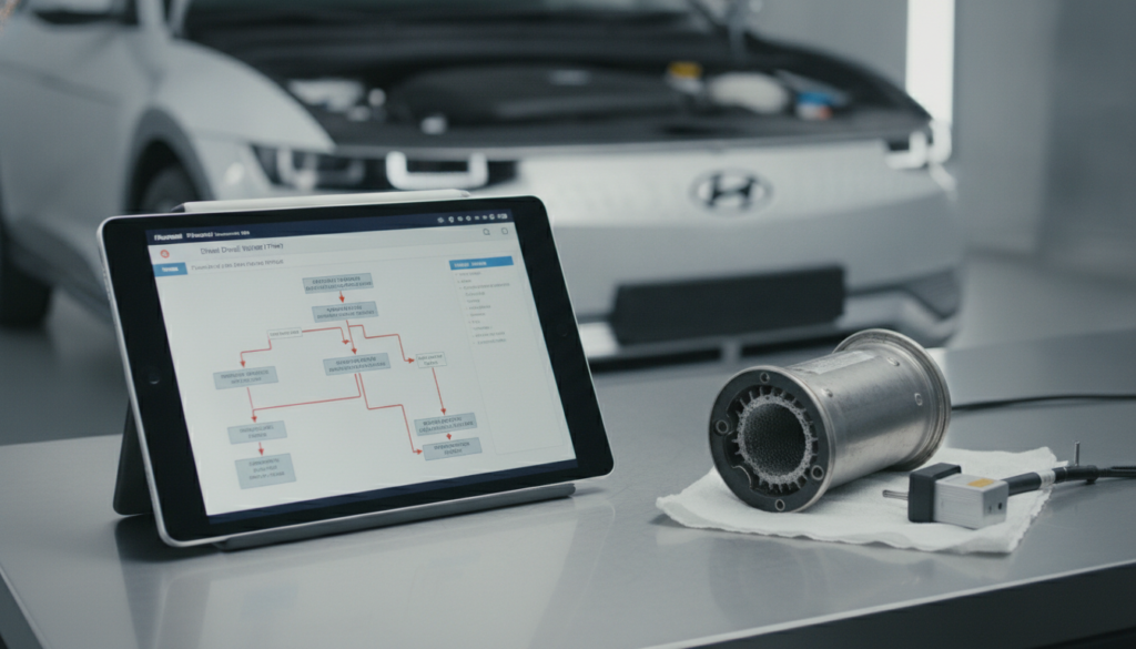
Electrical faults in Hyundai vehicles are rarely straightforward. A dead power window, a flickering dash light, or an intermittent no-start can each point to dozens of possible causes. Most DIY mechanics and independent technicians waste hours replacing parts that were never faulty in the first place.
The Hyundai ETM is a structured five-section document, distinct from standard manuals, that reduces diagnostic time through detailed schematics that generic guides lack. These manuals provide the wiring schematics, connector pinouts, component locations, and DTC flows required to fix electrical faults. Given the complexity of modern sensor networks, an exact-match ETM is vital for safe and effective circuit repair.
This post covers every section of the Hyundai electrical troubleshooting manual in the correct diagnostic order. You will learn how to trace a circuit from power source to ground, locate components on the vehicle, decode connector cavities, and map harness routing to find intermittent faults that no code scanner can detect.
Hyundai Electrical Troubleshooting Manual: The 5-Section Diagnostic System That Stops Guesswork

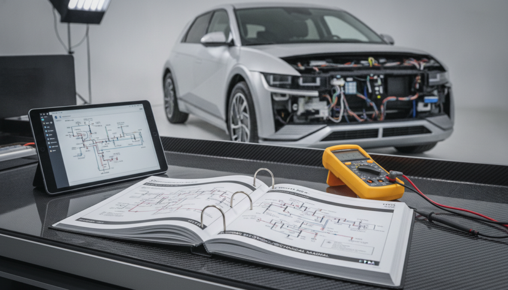
Alter Tag: A professional workspace featuring a Hyundai Electrical Troubleshooting Manual (ETM) and multimeter used for vehicle wiring diagnostics.
The Hyundai ETM is a purpose-built factory document that exists solely for electrical fault diagnosis. It is not a repair manual. It does not cover mechanical procedures, torque specs, or fluid capacities. Every page inside it serves one goal: showing you exactly how current flows through each circuit so you can identify where that flow is being interrupted.
The ETM vs. Generic Wiring Pages: What You Actually Get
|
Feature |
Hyundai ETM |
Generic Service Manual Wiring Section |
|
Schematic diagram depth |
Full circuit, power to ground, all switch positions |
Simplified overview only |
|
Component location index |
Listed with page references for every component |
Rarely included |
|
Connector cavity diagrams |
Full pin layout for every connector |
Not included |
|
Harness routing layouts |
Full vehicle harness map with splice locations |
Not included |
|
Ground distribution pages |
Dedicated ground schematic per zone |
Combined into single basic diagram |
|
Power distribution pages |
Full HOT AT ALL TIMES / HOT IN START breakdown |
Combined or absent |
|
Fault isolation value |
High: supports open, short, and voltage drop tests |
Low: insufficient for circuit-level diagnosis |
The ETM is organized into five major diagnostic sections. Each section feeds into the next. Skipping one causes misdiagnosis. The sections are: schematic diagrams, component location indexes, component locations, connector configurations, and harness layouts. Use them in that order every time.
Section 1: Read the Schematic Diagram First
Alter Tag: A professional workspace featuring a Hyundai Electrical Troubleshooting Manual (ETM) and multimeter used for vehicle wiring diagnostics.
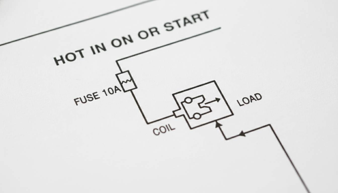
The schematic diagram is always your starting point. It shows the complete current path from the power source through every switch, load, and connection, down to the ground point. You need to understand this path before you touch a single wire.
Understand Power Source to Ground Path
Every schematic in a Hyundai ETM labels its power supply status at the top of the diagram. You will see labels like HOT AT ALL TIMES, HOT IN ON, or HOT IN START. These labels tell you exactly when that circuit receives voltage. Start at the power label, trace downward through the fuse, follow through each switch position, pass through the load (motor, lamp, or relay), and finish at the ground symbol.
A solid line in the schematic means the entire component is shown. A broken line indicates that only a portion is shown and that you need to cross-reference another page. The component name always appears at the upper right of its symbol box. Notes about its specific operating function follow the name directly.
Switch positions are shown for each state: for example, a stop lamp switch schematic shows the circuit open at rest and closed when the pedal is depressed.
This level of detail is what separates an ETM schematic from any aftermarket wiring guide. To understand how OBD-II codes map to these circuit paths, the post on reading OBD-II codes using manual flowcharts connects directly to this section-level reading approach.
Section 2: Use the Component Location Index Next

Alter Tag: A professional workspace featuring a Hyundai Electrical Troubleshooting Manual (ETM) and multimeter used for vehicle wiring diagnostics.
Once you understand the circuit from the schematic, you need to physically locate every component involved in that circuit on the vehicle. The component location index is the bridge between the schematic page and the real car.
The index lists every major component shown in the preceding schematic, every connector reference, every ground point, and every diode involved in that circuit. Each entry includes a page reference pointing to the component location illustration.
For example, an instrument cluster entry will show the reference page CL-15 and a connector reference such as I12 or M55.
Do not skip this index. Technicians who jump from the schematic directly to probing the car waste significant time because they cannot confirm component identity by visual inspection alone. The index gives you a numbered map before you open the bonnet.
Always write down the page references for each component, connector, and ground listed for your specific fault circuit before moving to Section 3.
Section 3: Match Components Using Location Illustrations
The component location illustrations give you a photograph or line drawing of the vehicle, showing exactly where each component from the index sits physically. These are not generic engine bay photos. They are marked-up diagrams with callout lines pointing to each specific item.
These illustrations make it easy to confirm you are probing the correct connector on a shared harness. On Hyundai models with multiple similar-looking connectors in close proximity, this section prevents the tester from testing the wrong circuit entirely. The illustration also shows surrounding components as spatial reference points.
Use the illustration to plan your physical access route before disassembly. If the component is behind a trim panel, the illustration will clarify that up front and prevent unnecessary teardown. Cross-reference the connector reference code shown in the illustration against Section 4 before you disconnect anything.
Section 4: Decode Connector Configurations Correctly
Alter Tag: A professional workspace featuring a Hyundai Electrical Troubleshooting Manual (ETM) and multimeter used for vehicle wiring diagnostics.
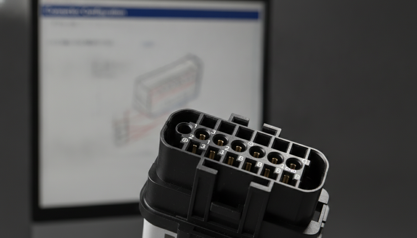
The connector configuration section shows the cavity layout for every multi-pin connector in the system you are diagnosing. This is one of the most frequently skipped sections, and skipping it is a common cause of test errors.
How to Read Cavity Numbers in Hyundai Connectors
Hyundai ETMs show both the male and female connector face views in this section. Cavity numbers are assigned from a fixed orientation: in most Hyundai ETMs, female connectors are numbered from the upper left to the lower right, and male connectors from the upper right to the lower left.
The numbering order is shown with small numbered diagrams in the general introduction section of the ETM.
Each cavity entry in the connector section tells you: the cavity number, the wire color at that cavity, the circuit it belongs to, and the component it connects to at the other end. This means you can confirm terminal identity before inserting a multimeter probe.
Incorrect probing can permanently damage connector terminals and create new faults. The post on decoding factory wiring color codes expands the color-coding system used across Hyundai circuits.
When testing with a multimeter, always use the correct back-probe method or manufacturer-approved test adapters.
Inserting probes into the front of a connector face without adapters risks permanent terminal damage. Always verify cavity polarity against the ETM connector diagram before applying voltage.
Section 5: Trace Faults Through the Harness Layout
The harness layout is the section that solves intermittent faults, parasitic drains, and problems that disappear when you touch the wiring. It shows the complete routing path of every major harness in the vehicle, including inline connector locations, splice points, and ground stud positions.
Ground faults are the most misdiagnosed category of Hyundai electrical problems. A corroded or loose ground stud can simultaneously affect multiple circuits because Hyundai shares ground points between systems.
The harness layout shows every G-code ground (G01, G02, etc.) and its physical location on the body or chassis. If your fault affects two unrelated systems, open the harness layout and check which ground points those systems share.
Splice locations shown in the harness layout are critical for finding shorts. A short to ground downstream of a splice will affect every branch circuit fed through that splice. Most generic wiring diagrams do not show splice locations at all. The ETM harness layout gives you each splice a reference number and places it on the vehicle outline.
For deeper guidance on using schematics to chase shorts and parasitic faults, the posts on tracing shorts with auto wiring diagrams and fixing parasitic drains with factory schematics provide hands-on procedures that pair directly with this ETM section. For ground point strategy specifically, finding hidden chassis ground points via manual is an essential companion read.
Testing Circuits With a Multimeter and ETM Data
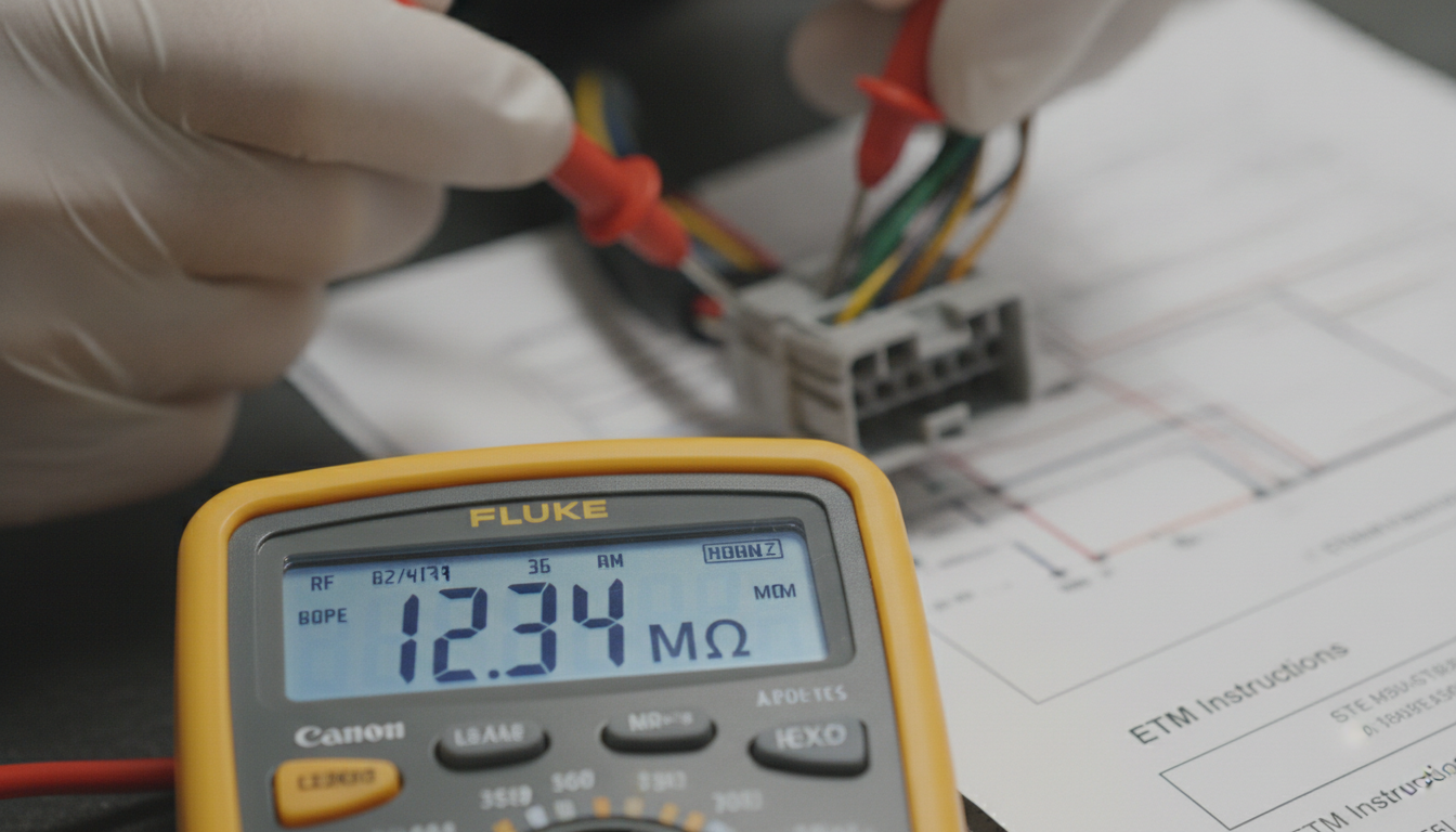
Alter Tag: A professional workspace featuring a Hyundai Electrical Troubleshooting Manual (ETM) and multimeter used for vehicle wiring diagnostics.
The ETM defines the exact tests required for every circuit. The general introduction section of each Hyundai ETM describes three approved test methods: voltmeter testing for circuits without solid-state modules, test lamp testing for basic voltage checks, and ohmmeter testing for continuity and resistance.
Do not use a test lamp on circuits that include solid-state modules such as the ECM, ABS module, or airbag control unit. A test lamp draws too much current for these circuits and can permanently damage the module. The ETM introduction section flags which circuits require meter-only testing.
For open circuit tests, connect one ohmmeter lead to each end of the suspected wire segment and check for continuity. For short-to-ground tests, disconnect both ends of the circuit, connect the ohmmeter between the wire and a known-good ground, and check the resistance.
Any reading below specification indicates an unwanted path to ground. The post on multimeter sensor testing via workshop manuals covers the voltage and resistance reference values used in Hyundai factory specifications.
Choose the Right Hyundai ETM for Your Model
The single most important rule for using a Hyundai ETM is model-year specificity. ETMs are not interchangeable between model years, even for the same nameplate. A 2001 schematic and a 2004 schematic for the same model can show entirely different circuit layouts due to mid-cycle electrical updates.
ETM Resources for Hyundai Europe Models
NXT Motors provides factory-level manual resources for the full range of Hyundai Europe models. The Hyundai Europe brand page is the best starting point for identifying which ETM applies to your specific vehicle. For owners of older models, dedicated pages cover the Hyundai Accent 1st Generation X3, the Hyundai Galloper, and the Hyundai Grand Santa Fe.
For van and MPV owners, resources are available for the Hyundai H-1, the Hyundai Trajet, and the Hyundai Terracan. Coupe and sports model owners can find ETM-related resources for the Hyundai Santamo and the Hyundai S-Coupe. Classic model owners should reference the Hyundai Pony page.
For hatchback and compact MPV owners, dedicated manual resources cover the Hyundai Matrix, the Hyundai Lantra, the Hyundai ix55, the Hyundai ix35, the Hyundai ix20, the Hyundai i30cw, and the complete Hyundai Europe workshop manual range, which covers the full catalog in one place.
Always confirm the model year printed on the ETM cover matches your vehicle's build date before starting any diagnostic work. The build date on the VIN plate, not the registration year, is the correct reference. The post on finding your factory service manual PDF by VIN explains how to use your VIN to match the correct document version to your vehicle's exact specifications.
Common Asked Questions about the Hyundai Electrical Troubleshooting Manual
What is the difference between a Hyundai ETM and the standard service manual?
The Hyundai ETM is a standalone electrical troubleshooting document, separate from the standard service manual. The service manual contains abbreviated wiring references used to support mechanical procedures.
The ETM contains full circuit-level schematics with power distribution pages, ground distribution pages, complete connector cavity diagrams, and harness routing layouts. An ETM schematic shows every switch position, every splice location, and every ground reference for a given circuit.
The service manual's wiring section does not include this level of detail. If you are diagnosing an electrical fault, the ETM is the correct document to use, not the service manual wiring appendix.
How do I know which section of the Hyundai ETM to open first?
Always open the schematic diagram section first. The schematic is the foundation of every electrical diagnosis because it shows you how current is supposed to flow through the circuit under normal conditions.
You cannot test a circuit correctly without first understanding its intended behavior. Once you have traced the intended current path on the schematic, you use the component location index to find the physical location of each component, then the connector configurations to confirm cavity identity before probing.
Skipping the schematic and going straight to the vehicle is the leading cause of misdiagnosis.
Can I use a Hyundai ETM for a different model year than my car?
No. Hyundai ETMs are model-year specific documents. Using a manual from a different production year, even for the same model name, is unreliable because circuit layouts, fuse assignments, connector positions, and ground points change between production years.
Mid-cycle updates in particular introduce wiring revisions that are not documented in earlier ETM editions. Always verify the ETM cover states the exact model year of your vehicle before using any schematic or component location data from it.
Your vehicle's build date, found on the VIN plate, is more accurate than the registration year for matching the correct ETM edition.
Why does my Hyundai ETM show different connector numbering than I see online?
Connector numbering in Hyundai ETMs follows a strict orientation convention that varies across body-side, harness-side, and in-line connectors. Female connectors are typically numbered from upper left to lower right when viewed from the wire side, while male connectors run from upper right to lower left.
Online diagrams from aftermarket sources frequently use incorrect orientations or combine connector views from different model years. Always use the orientation guide shown in the general introduction section of your specific ETM to confirm numbering direction before probing any connector cavity.
What tools do I need to use a Hyundai ETM for electrical testing?
The ETM's general introduction section specifies three core testing tools. A digital multimeter is required for voltage, resistance, and continuity tests on all circuits, and is the only tool permitted on circuits with solid-state modules such as the ECM or ABS unit.
A 12-volt test lamp can be used on basic circuits without solid-state components to quickly check for the presence of voltage. A jumper wire is used to temporarily bypass suspected open circuits to confirm the fault location.
A short finder tool is also mentioned in some Hyundai ETMs for locating shorts to ground without disconnecting components. Do not substitute a test lamp for a multimeter on any circuit that includes an electronic control module.