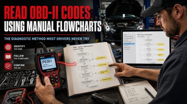
When your check engine light illuminates, and a scan tool reveals a code like P0301, the next step is often where drivers falter. Many resort to haphazardly replacing parts or paying professional diagnostic fees for information they essentially already possess.
Using the vehicle-specific diagnostic flowcharts in repair manuals provides a systematic approach to identifying root causes. By following these diagnostic trees, which transition from initial MIL verification to detailed component testing, and understanding the 5-digit DTC structure, you can replace guesswork with structured troubleshooting.
This tutorial explains the proper use of manual flowcharts to accurately interpret OBD-II data, guiding you from the initial code retrieval to a verified, long-term repair.
Read OBD-II Codes Using Manual Flowcharts: The Structured Approach Mechanics Actually Use
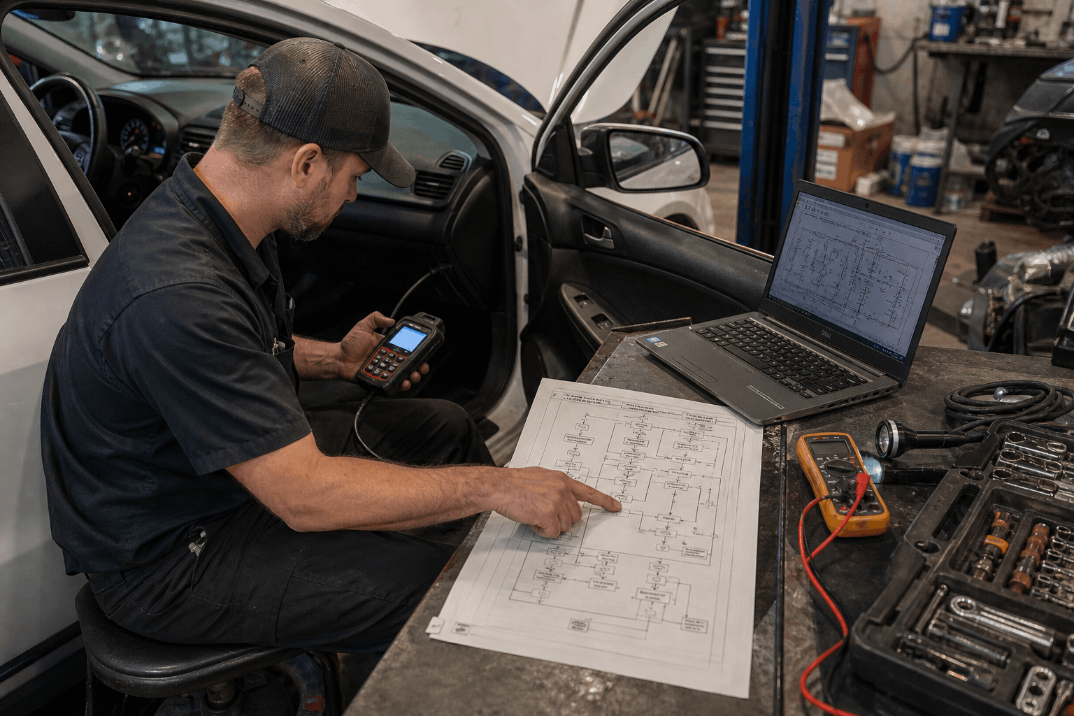
Most DIYers treat OBD-II codes like a final answer. Experienced technicians treat them like a starting point. There is a significant difference between those two mindsets, and it shows up in the repair bill.
Manual flowcharts exist to bridge that gap. They are diagnostic trees built into factory service manuals and trusted repair guides, designed to walk you through every possible cause of a given DTC until you find the right one. Used correctly, they turn a confusing alphanumeric code into a clear, testable action plan.
Step 1: Connect the Scanner and Pull the Codes Right
Before any flowchart can help you, you need accurate data from the vehicle.
Locate the OBD-II port, a 16-pin trapezoidal connector, which is almost always found under the driver’s side dashboard near the steering column. Plug in your code reader or scan tool with the ignition off, then turn the key to the “on” position without starting the engine.
- Navigate to “Read Codes” or “Diagnostic Trouble Codes” in the scanner menu
- Note both Active Codes (currently triggering the MIL) and Pending Codes (occurred at least once)
- Record every code shown — multiple codes often share a single root cause
- Check Freeze Frame Data to see the engine conditions at the moment the fault occurred
Freeze frame is often overlooked, but it shows the engine load, RPM, fuel trim, and coolant temperature at the time of the fault. That information is critical for choosing the correct diagnostic path in your manual’s flowchart.
Step 2: Decode the DTC Structure Before Opening the Manual
Every OBD-II code follows a fixed format. Reading it correctly saves you from jumping to the wrong flowchart.
|
Code Position |
What It Tells You |
|
First Letter |
System: P (Powertrain), B (Body), C (Chassis), U (Network) |
|
Second Digit |
0 = Generic/SAE standard, 1 = Manufacturer-specific |
|
Third Digit |
Subsystem (1=Fuel/Air, 2=Injector, 3=Ignition, 4=Emissions…) |
|
Fourth & Fifth |
Specific fault number within that subsystem |
So P0301 means: Powertrain, generic SAE code, ignition subsystem, cylinder 1 misfire detected. That points you to a very specific section of the misfire diagnostic flowchart in your repair manual.
Manufacturer-specific codes (P1xxx) require your vehicle’s own service manual, not just a generic OBD-II list. This distinction matters a lot when choosing which flowchart to follow.
Step 3: Find the Right Flowchart in Your Repair Manual

This is where most DIY repairs go wrong. People look up the code description online and start replacing parts based on what “commonly causes” that code. That approach is expensive and unreliable.
A proper repair manual will contain a dedicated diagnostic flowchart for the most common DTCs. These are sometimes labeled as:
- Pinpoint Tests (Ford)
- Diagnostic Procedures (GM, Toyota)
- DTC Diagnosis charts (Honda, Mazda)
- Strategy-Based Diagnostics (general manufacturer term)
Open your manual to the section matching your fault code’s system. For a P0301, you would go to the Ignition/Misfire section. The flowchart entry point always starts with verifying the concern and gathering live data, not replacing components.
If you are using a Haynes or Chilton manual rather than a factory service manual, look for “Fault Code Diagnosis” or “Troubleshooting Charts” in the relevant chapter. The depth varies by publisher, but the diagnostic logic is the same.
For a deeper look at where to source genuine diagnostic documents, this guide, Where to Download Genuine OEM Workshop Manuals, covers the most trusted sources available today.
Step 4: Follow the Flowchart Logic — Decision by Decision

This is the core of strategy-based diagnostics. A flowchart is a binary decision tree. Each node asks a yes/no question based on a measurable test.
Here is how a typical P0301 misfire flowchart might begin:
- Are there any related codes stored alongside P0301? (Yes/No)
- Yes: Diagnose shared-circuit codes first before addressing the misfire
- No: Proceed to step 2
- Is the misfire present at all cylinder counts or isolated to cylinder 1? (Check live data)
- All cylinders: Suspect fuel pressure, intake vacuum, or timing
- Only cylinder 1: Proceed to spark, injector, and compression tests for that cylinder
- Does swapping the coil to another cylinder move the misfire? (Yes/No)
- Yes: Faulty ignition coil confirmed, replace and retest
- No: Coil is not the cause — proceed to injector flow test
Each decision eliminates a possible cause. You are not guessing. You are testing and eliminating branches one at a time.
Never skip a step in the flowchart, even if you are confident you know the answer. The flowchart is built by engineers who already know the common shortcuts that lead to misdiagnosis.
Step 5: Use Live Data and Sensor Readings to Answer Each Question
Flowcharts are only as useful as the data feeding into them. Many diagnostic questions require actual sensor readings from your scan tool or a digital multimeter (DMM).
|
Test Type |
What to Measure |
Tool Needed |
|
Spark test |
Spark intensity and consistency |
Spark tester |
|
Injector pulse |
Signal voltage and duty cycle |
DMM / oscilloscope |
|
Compression test |
PSI per cylinder (should be within 10% of each other) |
Compression gauge |
|
Fuel trim |
Short-term and long-term STFT/LTFT via live data |
OBD-II scanner |
|
O2 sensor switching |
Switching frequency, rich/lean response |
Scan tool live data |
Your manual will specify exact values for each test for your particular engine. Generic internet specs are not reliable here. Factory tolerances vary significantly between engine families, and following the wrong spec can send you down the wrong diagnostic branch.
Step 6: Verify the Repair Before Closing the Job
This step gets skipped more than any other. Once you identify and fix the fault, the flowchart is not done yet.
Most OBD-II diagnostic procedures end with a verification cycle:
- Clear the DTC from the ECU memory using your scanner
- Perform a drive cycle specific to that monitor (your manual will describe the required conditions)
- Re-read codes after the drive cycle completes
- Confirm the relevant readiness monitor shows “Complete” or “Ready.”
If the code returns, the flowchart was not fully resolved, or the wrong branch was taken. Do not replace additional parts before retracing your diagnostic steps. Chasing a returning code with parts is how a $40 repair turns into a $400 one.
For those relying solely on free online resources versus structured manual content, it is worth understanding the trade-offs outlined in this breakdown of Are Free Online Car Repair Manuals Safe, particularly when the diagnosis involves emission systems or complex sensors.
When a Code Needs Professional Escalation
Manual flowcharts are designed for the most common DTCs, but some fault paths require dealer-level equipment.
Consider professional escalation when:
- Multiple unrelated codes appear simultaneously. This often indicates a wiring harness, ground, or PCM issue that requires advanced network diagnostics
- The flowchart leads to the PCM (Powertrain Control Module) itself, as a suspected fault, PCM replacement, or programming requires specialized equipment and calibration
- Safety system codes appear, including ABS, SRS airbag, or electronic stability control. These systems carry serious liability if misdiagnosed
The decision between DIY diagnostics and professional help is worth careful consideration. This comparison of Digital Car Manuals vs. Mechanic Advice breaks down the trade-offs in practical terms most car owners can use.
Conclusion
Reading OBD-IIcodes is straightforward. Knowing what to do after you read them is the skill that actually saves you money. A scan tool gives you the fault code the repair manualflowchart gives you the diagnostic roadmap.
Follow each decision point methodically, feed real sensor data into each branch, and verify the repair before clearing the code. That is how professional technicians approach every DTC, and it is exactly how you should approach yours.
Frequently Asked Questions
Not reliably. Manufacturer-specific codes (those starting with P1, B1, C1, or U1) are proprietary and can mean very different things across brands. For example, a P1300 on a Toyota refers to an igniter circuit fault, while the same code on a different make points to a completely unrelated system.
Always use a vehicle-specific service manual or factory diagnostic guide when working with manufacturer codes. Generic flowcharts are designed for SAE standard codes (P0, B0, C0, U0) and will not account for brand-specific sensor configurations, wiring layouts, or ECU logic.
Using the wrong flowchart for a manufacturer code typically results in misdiagnosis, wasted parts, and a recurring problem.
A pending code has been detected once but has not yet caused the check engine light to activate. The ECU is waiting to see the fault occur a second time before committing it as an active DTC.
Active codes have met the threshold for confirmed failure and have triggered the malfunction indicator light (MIL). When following a diagnostic flowchart, you should note pending codes alongside active ones.
Sometimes, a pending code reveals the actual root cause of an active code in a related system. Factory service manuals often include specific guidance on how to interpret pending codes in the context of the primary fault you are diagnosing.
No. This is the most common misunderstanding in DIY diagnostics. An OBD-II code identifies which circuit or system reported an out-of-range condition, not which component caused it.
A P0171 (System Too Lean) could point to a dirty MAF sensor, a vacuum leak, a weak fuel pump, a failing O2 sensor, or clogged injectors. The code narrows the territory; the flowchart and subsequent testing tell you the specific cause.
Replacing parts based solely on the code description without following the diagnostic procedure is one of the most expensive mistakes a car owner can make.
Readiness monitors are internal self-tests that the ECU runs on emission-related systems during normal driving. After a code is cleared or the battery is disconnected, these monitors reset to “incomplete.”
Most state emissions inspections require the majority of applicable monitors to show “complete” before the vehicle can pass. If you clear codes before an inspection without completing the required drive cycle, the car will fail even if the underlying fault has been repaired.
Your repair manual or the local DMV website should list the specific drive-cycle conditions required to complete each monitor on your vehicle.
Yes, and this is often overlooked during diagnosis. A blown fuse connected to the diagnostic link connector (DLC), corroded pins in the OBD-II port, or a damaged wiring harness near the port can all prevent communication between the scanner and the ECU.
If your scan tool shows “no communication” or “link error,” start by checking the fuses associated with the DLC and PCM in your vehicle’s fuse panel.
Your repair manual will list the specific fuses by number and amperage. If the fuses are intact, inspect the port physically for bent or corroded pins before suspecting a deeper ECU issue.