
A failing alternator voltage drop can quietly kill your battery, trigger mystery warning lights, and leave you stranded without a clear cause. The testing steps most guides show are incomplete, and that gap leads to expensive misdiagnoses.
Diagnose this by testing positive and negative circuits with a DVOM (2V DC range) at 2000 RPM under full electrical load. Resistance is excessive if the difference between the alternator and the battery exceeds 0.3V (300 mV).
This guide walks through every step in order, from tool setup to fault isolation, so you can test correctly the first time.
Alternator Voltage Drop Testing Steps: The Method That Actually Finds the Problem
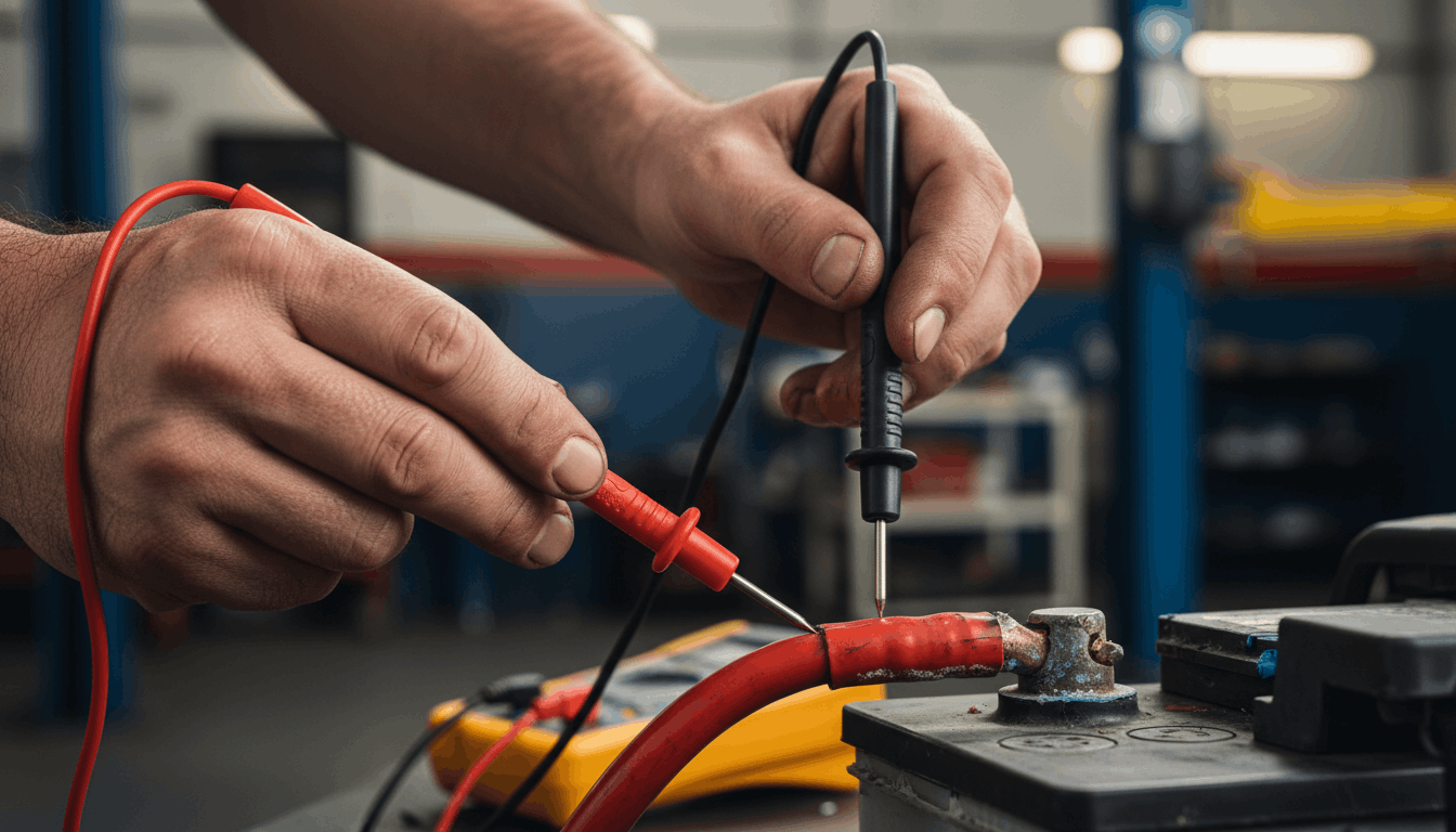
Many technicians jump straight to replacing the alternator when the charging system underperforms. That is a costly mistake, and it is avoidable.
A proper alternator voltage drop test measures the resistance hiding inside your cables, terminals, and connections, not just the alternator output itself. When resistance builds up in the charging circuit, the alternator cannot deliver its full current to the battery, even if it is generating good voltage. These steps target that exact problem before you touch a single part.
Before You Start: Tools and Pre-Test Conditions
Skipping pre-test checks leads to false readings. Spending two minutes here saves an hour of confusion later.
A digital voltmeter or DVOM is the only tool you need for this test. Set it to DC voltage, and if it requires manual range selection, set it to the 2V DC scale. That range gives you the resolution needed to catch small but damaging drops.
Before testing, confirm:
- The battery is fully charged (12.4V or above at rest)
- Battery terminals are clean and tight
- Engine coolant temperature is normal
- No rear electric defroster is running (it can skew readings on some models)
If your battery is weak, charge it first. A depleted battery changes the alternator load, making your voltage drop readings unreliable. For a deeper look at pre-test diagnostics, the alternator testing procedures explained guide covers battery warning light checks that often indicate charging circuit faults before you even pick up a meter.
Step 1: Load the Charging System Properly

A voltage drop only shows up under real current flow. Testing at idle with nothing turned on tells you almost nothing.
Start the engine and bring it to 1,800-2,000 RPM. Turn on the headlights (high beam), air conditioner or heater at full speed, and any other high-draw accessories. This forces the alternator to push near-maximum current through the circuit, which is exactly when hidden resistance becomes visible.
Why RPM matters:
|
Engine Speed |
Alternator Output |
Test Validity |
|
Idle (600-800 RPM) |
Low output |
Not reliable |
|
1,800-2,000 RPM |
Near full output |
Accurate |
|
Above 2,500 RPM |
Full output |
Also accurate |
Keep the RPM steady throughout both the positive and ground circuit tests. Fluctuating engine speed causes the readings to bounce, making it hard to record a clean result.
Step 2: Test the Positive Power Circuit Voltage Drop
This step isolates resistance between the alternator output and the battery positive terminal. It is the first circuit to check.
Connect your DVOM red lead to the alternator output stud (the B+ terminal, which is the large bolt where the main output cable connects). Connect the black lead to the positive battery terminal. With the engine at 2,000 RPM and all loads on, read the voltage drop.
Acceptable readings for the positive circuit:
- Below 0.2V: Excellent connection, no resistance problem
- 0.2V to 0.5V: Within acceptable range for most vehicles (check your repair manual)
- Above 0.5V: Excessive resistance detected, further isolation needed
If you read above 0.5V, do not replace the alternator yet. Move the black lead, step by step, from the battery toward the alternator: the battery positive post, then the fusible link, then each junction point, then the output stud. The largest voltage drop between two points is where the resistance is.
Common culprits here include corroded fusible links, loose cable ends, and oxidized junction block terminals. For tracing these faults through wiring, wiring diagrams to trace shorts provide a reliable method for mapping the path from the alternator to the battery.
Step 3: Test the Negative Ground Circuit Voltage Drop

The ground side is where most technicians stop looking, and it is where many charging faults actually hide.
Connect the DVOM red lead to the negative battery terminal. Connect the black lead to the alternator housing (the metal body of the unit, not a painted surface). With the engine still at 2,000 RPM and loads still on, read the result.
Acceptable readings for the ground circuit:
- Below 0.2V: Ground path is solid
- Above 0.2V: Resistance exists in the ground circuit
- Above 0.5V: Serious ground fault, inspect all connection points
If the reading is high, check the alternator mounting bolts first. They often serve as the primary ground path. Loose or rusty bolts create significant resistance. Some alternators use a separate ground strap instead of relying on the mounting points. If yours has one, test the voltage drop across that strap individually.
Also, inspect the engine ground strap that runs from the engine block to the chassis. A corroded or broken engine ground affects the entire charging circuit, not just the alternator. The hidden chassis ground points via manual resource are useful here for locating ground attachment points that are not obvious under the hood.
Step 4: Isolate the Fault Point
A high reading confirms resistance exists. This step tells you exactly which component is causing it.
With the engine running and loads applied, move one DVOM lead at a time along the circuit. Test each cable section, terminal connection, and junction. The segment that shows the highest voltage drop is the fault.
What you are looking for:
- Corroded terminals: Greenish or white buildup at the cable end
- Loose connections: Any terminal that moves when pushed lightly
- Damaged cable: Look for melted insulation or swollen sections indicating heat damage from sustained high resistance
- Corroded fusible links: These often look intact but have internal corrosion
Once you find the problem segment, clean the terminal connections with a wire brush, apply electrical contact grease, and retest. If a cable is internally corroded, replacing it is the only fix. Cleaning the outside does not restore current flow through a degraded conductor.
For any sensor-related faults that arise during this process, multimeter sensor testing per workshop manuals shows how to extend your DVOM testing to related sensors in the charging circuit.
Step 5: Verify and Record the Final Readings

After any repair, retest immediately to confirm the problem is resolved. Do not assume a clean terminal fixes the reading.
Run the engine back to 2,000 RPM with all loads on and record both circuit readings again. Both should now be within specification. Write down the results along with the date and vehicle mileage. This baseline becomes useful if the charging system develops issues down the road.
Final reading targets after repair:
|
Circuit |
Target Reading |
|
Positive power circuit |
Below 0.3V |
|
Negative ground circuit |
Below 0.2V |
|
Total system drop |
Below 0.5V |
If readings remain elevated after cleaning the connections, inspect the charging circuit for relay-related issues. The relay testing procedures manual pinouts guide covers charge-related relay faults that can mimic voltage drop symptoms.
Conclusion
Alternator voltage drop testing is not a complicated process, but it does require doing the steps in order, under load, with the right meter settings. Most charging system faults are not inside the alternator itself. They are in the cables, terminals, and ground connections surrounding it.
Test both circuits every time. Record your readings. And if the numbers are off, isolate before you replace. A clean, accurate diagnosis takes less than ten minutes and can save you hundreds of dollars on a part you never needed.
Frequently Asked Questions
The acceptable voltage drop for the positive power circuit is generally 0.5V or less, though many manufacturers specify tighter tolerances of 0.2V to 0.3V. The ground circuit should stay at or below 0.2V. Total system drop across both circuits combined should remain under 0.5V.
Always check your vehicle-specific repair manual because some models have stricter limits. Running above the specified threshold means the alternator is working against resistance and cannot deliver the full charging current to the battery under load.
Yes, and this is one of the most common misdiagnoses in charging system work. A corroded or loose ground connection at the alternator housing or engine block creates measurable resistance. That resistance limits current flow and produces the same symptoms as a weak alternator: undercharging, battery drain, and dim lights under load.
The voltage drop test on the negative circuit will catch this immediately. Always test both circuits before concluding the alternator itself is bad, as replacing a good alternator in a circuit with ground issues will not solve the problem.
Running the engine at 2,000 RPM ensures the alternator is producing near its maximum output. At idle speeds, the alternator operates at reduced capacity and low current, making small-resistance faults invisible.
Voltage drop is measurable only when a significant current is flowing through the circuit. By loading the system with headlights, HVAC, and other accessories at 2,000 RPM, you create conditions that closely match real-world worst-case current demand.
This is when hidden resistance in cables and connections becomes electrically significant enough to show up on the meter.
When resistance in the charging circuit forces the voltage at the battery to stay low, the alternator’s internal voltage regulator compensates by pushing the alternator to produce maximum output continuously.
This sustained high-output operation generates heat inside the alternator windings and diode pack, accelerating wear. Over time, the diodes fail, the brushes wear faster, and the stator can overheat.
Ironically, a corroded cable or bad terminal connection, something that costs a few dollars to fix, is often the root cause of a complete alternator failure that costs several hundred dollars to address.
Modern vehicles with smart charging systems or battery management units (BMU) regulate charging voltage dynamically based on battery state and temperature. The basic voltage drop testing steps using a DVOM are the same, but interpreting the results requires knowing that output voltage may intentionally vary.
On these vehicles, the alternator may output anywhere from 12.5V to 15.5V depending on the control strategy.
The focus should still be on the drop between the B+ stud and the battery terminal rather than absolute output voltage, since excessive resistance in the circuit remains the fault indicator regardless of the control strategy in use.