
Testing sensors with a multimeter without a workshop manual risks using generic values that differ from your ECU’s specific requirements. Since sensor issues cause over 40% of engine fault codes, precise test values are essential.
Always retrieve the DTC and consult the manual for engine-specific data before measuring. Accurate diagnosis depends on manufacturer-specific pinouts and expected electrical signals.
This guide explains how to use multimeter functions for various sensors, interpret workshop manual specs, and avoid common testing errors.
Multimeter Sensor Testing via Workshop Manuals: Why the Spec Table Changes Everything
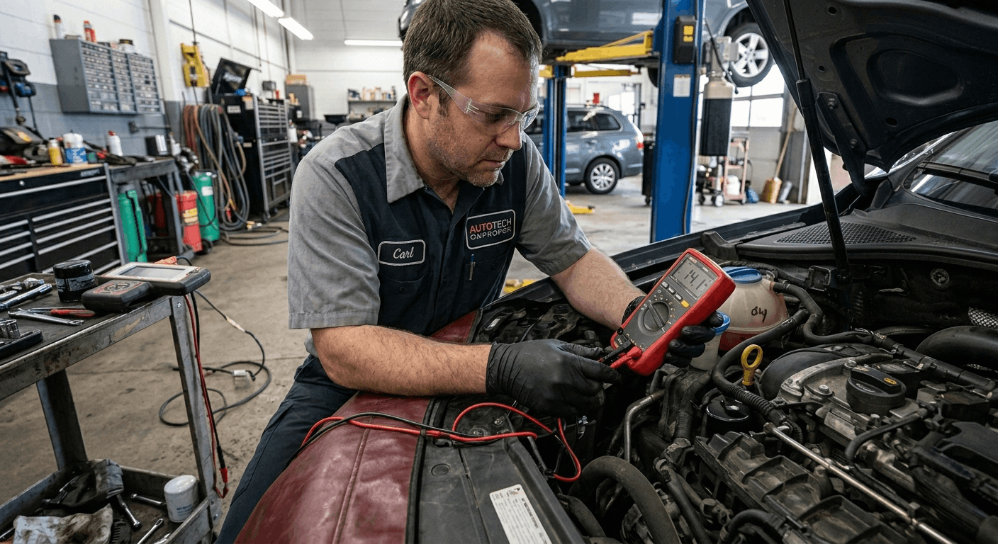
Generic sensor test values circulate widely online, and most of them are close enough to cause real diagnostic problems. A coolant temperature sensor on a Toyota 2GR-FE engine follows a different resistance curve than the same sensor category on a Honda K-series. Using the wrong curve means a healthy sensor looks out of spec, and a failing one looks fine.
Workshop manuals contain the exact resistance tables, reference voltage ranges, and output signal specifications for every sensor in the vehicle indexed by engine code and model year. Without that document open during multimeter testing, every reading is an educated guess measured against uncertain criteria.
Step 1: Set Up the Multimeter Correctly Before Any Test
The most common cause of inaccurate sensor readings is the wrong multimeter setting — not a faulty sensor. Before touching a connector, confirm the correct test mode and range for the measurement you are about to take.
Multimeter functions used in sensor testing and when to use them:
|
Function |
Symbol |
Used For |
Caution |
|
DC Voltage |
V⎓ |
Most sensor output signals, reference voltage checks |
Never test resistance on a powered circuit |
|
Resistance / Ohms |
Ω |
Coolant temp sensor, fuel level sender, ignition coil |
Ignition must be OFF, component unplugged |
|
Continuity |
♐ or speaker icon |
Wiring harness, ground paths, fuse integrity |
Use with ignition OFF only |
|
AC Voltage |
V∼ |
Crankshaft and camshaft position sensors (magnetic type) |
Not used for Hall-effect sensors |
|
Frequency / Hz |
Hz |
MAF sensors with frequency output, wheel speed sensors |
Requires engine running or wheel movement |
Consult your workshop manual for the specific measurement type required for each sensor. Digital Hall-effect crank sensors need frequency or DC voltage modes, while magnetic reluctor types require AC voltage. Selecting the incorrect mode can result in a false zero reading, leading to an incorrect open-circuit indication in a functional sensor.
Always verify your multimeter leads are in the correct port before testing. Using the non-fused port for current measurements will blow the meter’s internal fuse and potentially damage the circuit you are testing.
Step 2: Read the Workshop Manual Spec Table for the Target Sensor

Before connecting any probe, find the sensor specification table in your workshop manual. These tables appear in the Engine Management, Engine Controls, or Electrical Diagnosis section the exact location varies by manufacturer.
The spec table will show:
- Test condition: Key-on engine-off (KOEO), key-on engine-running (KOER), or specific temperature/load conditions
- Connector pin number: Which terminal to probe and which to use as reference
- Expected value: The actual number your multimeter should display if the sensor is healthy
- Pass/fail threshold: The acceptable range, not just a single number
Finding the correct factory manual documentation for your VIN is the first step before any sensor work begins. This guide to Find Your Factory Service Manual PDF by VIN shows how to quickly locate the right document.
If you need to evaluate which type of workshop manual provides the most accurate sensor specification tables, a factory service manual versus an aftermarket guide, this practical comparison of OEM vs Aftermarket Manuals for DIY clarifies the accuracy differences relevant to electrical diagnostics.
For the most reliable sources of verified, year-specific factory service documentation, this resource on Where to Download Genuine OEM Workshop Manuals remains the best starting point.
Step 3: Test the Five Core Sensor Types Correctly
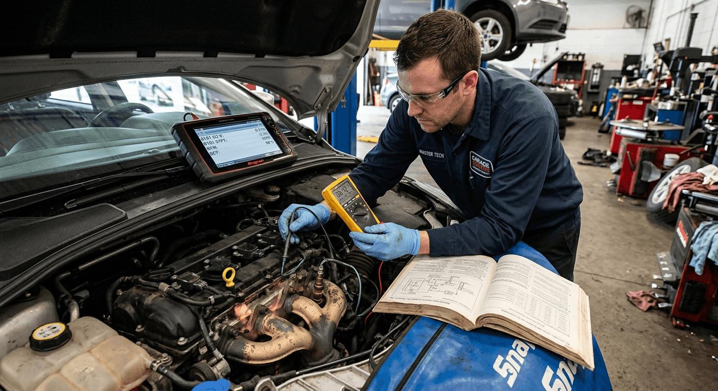
Each sensor category requires a different multimeter approach and a different section of the workshop manual. Here is how to approach each one using the factory specification as your reference.
Oxygen Sensor (O2)
Set the multimeter to DC voltage, 2V range. Back-probe the signal wire with the engine at operating temperature. A healthy upstream O2 sensor switches between 0.1V (lean) and 0.9V (rich) several times per second.
A reading that stays near 0.45V indicates a lazy or contaminated sensor that is not responding to changes in the mixture.
Check the heater circuit resistance with the ignition off. Your workshop manual will specify the expected range, typically 4 to 14 ohms, depending on the manufacturer.
Coolant Temperature Sensor (CTS)
Set the multimeter to resistance (ohms) with the ignition off and the sensor connector unplugged. The CTS is a negative temperature coefficient (NTC) resistor, whose resistance decreases as temperature increases.
Your workshop manual will include a resistance-temperature table. At 20°C (cold engine), most CTS units read between 2,000 and 3,000 ohms.
At 80°C (normal operating temp), the reading drops to approximately 200-400 ohms. A reading of OL (open loop) at any temperature indicates an open circuit inside the sensor.
Throttle Position Sensor (TPS)
Set the multimeter to DC voltage with the ignition on and engine off. Back-probe the signal wire and ground pin as specified in the workshop manual.
At idle (closed throttle), expect 0.5-1.0V. As the throttle opens, the voltage should climb smoothly to 4.5-4.8V at wide-open throttle.
Any dropout, jump, or dead spot in the voltage sweep indicates a worn resistive track inside the TPS. The manual will confirm the acceptable sweep range for your specific unit.
Mass Air Flow Sensor (MAF)
There are two MAF types, each requiring different multimeter settings. Voltage-output MAF sensors: set to DC voltage, check the 5V reference supply and the signal output at idle (typically 0.8V to 1.5V, rising under load).
Frequency-output MAF sensors: set to Hz mode and check for a range of 30 to 150 Hz at idle. Your workshop manual will specify which type your vehicle uses and the exact idle frequency.
Measuring a frequency sensor in voltage mode produces a false average reading that cannot confirm sensor health.
Crankshaft Position Sensor (CKP)
Magnetic CKP sensors produce an AC sine wave set to AC voltage and check the output while cranking. Your workshop manual will specify the minimum acceptable AC voltage during cranking (typically 0.5V AC or higher).
Hall-effect CKP sensors produce a digital square wave set to a DC voltage and confirm that the signal switches cleanly between 0V and the reference voltage (5V or 12V, depending on design) during cranking.
A multimeter alone is limited for CKP diagnosis; an oscilloscope shows the waveform shape more accurately, but the presence or absence can still confirm a dead sensor quickly.
Step 4: Use Back-Probing Correctly — Never Pierce Wires
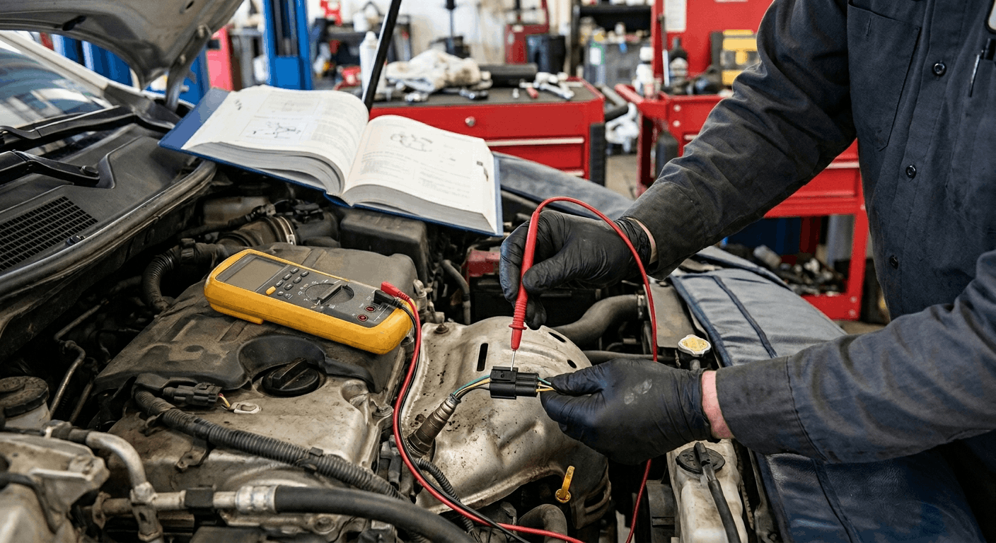
The physical technique of connecting the multimeter probe to a live sensor connector matters as much as the test values. Incorrect probing damages connectors, causes intermittent faults, and invalidates test results.
Correct probing technique:
- Use a back-probe tool, a thin, blunt probe that slides alongside the terminal through the rear of the connector without widening the pin socket
- Never insert a sharp probe tip directly into the front of the connector terminal, even slight widening reduces contact force and creates an intermittent fault that appears after reassembly
- Never pierce the wire insulation with a sharp probe. This creates a moisture entry point that corrodes the conductor from the inside, producing a fault weeks after the repair
- Connect the multimeter black lead to chassis ground or the connector’s dedicated ground pin, as specified in the workshop manual, not to the battery negative, which can introduce minor voltage differences on long harness runs
Your workshop manual will show a connector diagram for each sensor with pin numbers labeled. Match pin numbers in the diagram to physical pin positions in the connector before probing. On multi-pin connectors, a misidentified pin can produce a reading from a completely different circuit.
For vehicle-specific connector diagrams and sensor pin assignments matched to your exact build specification, VIN-Specific Manuals eliminate the risk of using a slightly incorrect variant document.
Step 5: Interpret Readings Against Workshop Manual Pass/Fail Criteria
A reading that falls within a generic online range but outside your workshop manual‘s specified tolerance will still produce a fault code on the next drive cycle. The manual defines what passes and fails — not the internet.
Common misinterpretations and their actual meaning:
- CTS reads within the generic range, but fault code returns: The factory resistance-temperature curve for your specific engine may have tighter tolerances than generic guides show. Check the manual‘s exact spec table at the actual measured engine temperature
- O2 sensor reads switching, but lean trim codes persist: Check the workshop manual for switching frequency specification. Some manufacturers specify a minimum switching cycle rate per second. A slow-switching sensor passes a basic voltage test but fails the speed criterion
- MAF sensor voltage reads 1.2V at idle. Is that correct?: Only the manual can answer this. Idle voltage varies by engine displacement and MAF housing diameter. 1.2V is correct for some applications and low for others
- TPS sweep looks smooth, but hesitation code remains: Some TPS specifications require the sweep to complete within a specific voltage range at partial throttle. Check the manual for partial-load voltage windows
For those still building their diagnostic reference library and uncertain which type of workshop documentation best matches their repair level and vehicle complexity, this overview of How to Choose the Right Workshop Repair Manual for Your Vehicle provides clear, experience-based guidance.
If free online manual sources are part of your documentation approach for sensor specification data, this practical guide, “Are Free Online Car Repair Manuals Safe,” covers the quality gaps that specifically affect electrical testing accuracy.
Conclusion
Multimeter sensor testing is precise when it is built on precise reference data. The workshop manual provides the test conditions, connector pin assignments, the correct measurement mode, and the exact pass/fail thresholds, none of which are reliably available from generic online sources.
Set the multimeter correctly. Find the spec table first. Test under the conditions specified in the manual. Compare against factory tolerances. That process completes the diagnosis the first time, without unnecessary part replacements or returning fault codes.
Frequently Asked Questions
A basic digital multimeter handles the majority of common sensor tests DC voltage for signal checks, resistance for temperature sensors and coils, and continuity for wiring integrity. An automotive-specific multimeter adds functions such as RPM measurement, duty cycle, pulse width, frequency mode (for MAF and wheel-speed sensor testing), and Min/Max recording.
For a MAF sensor that outputs a frequency signal rather than a voltage signal, a basic DC-voltage meter will produce an averaged reading that cannot confirm sensor health. If your workshop manual specifies a frequency or duty cycle test for a specific sensor, you need a meter with those functions.
For most NTC temperature sensors, throttle position sensors, and O2 voltage tests, a basic DMM is entirely sufficient.
The accuracy gap matters most on modern vehicles with model-year variants and trim-specific configurations. Online sensor specifications often are sourced from a generic specification that covers a range of model years or engine displacements.
Your workshop manual contains the exact resistance-temperature curve, voltage-sweep range, or frequency-output specification for your specific engine code and emissions variant. A CTS resistance value published online for a 2.4L engine may differ from the actual spec for a 2.4L with the California emissions package, which uses a different sensor supplier.
Using the wrong specification on a P0115 coolant temperature diagnosis can lead to replacing a healthy sensor or missing a fault that sits just outside the generic range.
Back-probing means inserting a thin, blunt instrument, a dedicated back-probe tool, or a very fine-gauge solid wire alongside the connector terminal through the rear of the connector housing, making contact with the terminal without altering its geometry.
Piercing the wire insulation means pushing a sharp probe tip directly through the insulation to contact the conductor inside. Piercing creates a permanent entry point for moisture and contaminants, which can corrode the conductor internally over weeks or months, generating an intermittent fault that is extremely difficult to locate afterward.
Back-probing leaves no damage. Every workshop manual describes the correct probing method for harness connector testing. Always use the method specified for each connector type.
Yes, and this is common with dynamically failing sensors rather than statically failing ones. A throttle position sensor may show a clean resistance sweep at room temperature but develop a dead spot under heat from the engine bay.
An O2 sensor may show correct switching voltage during a static back-probe test but respond too slowly under actual combustion conditions, failing the ECU’s switching frequency criterion. A MAF sensor may read a correct idle voltage but produce an inconsistent frequency output under load, which is revealed only by an oscilloscope or a bidirectional scan tool during a drive cycle.
The multimeter test confirms the sensor is not completely dead. The workshop manual‘s live data specifications, checked via a scan tool during actual operating conditions, confirm whether the sensor meets dynamic performance criteria.
Yes, always. Most engine sensors operate on a 5V reference supply from the ECU. If the reference voltage is absent, low, or unstable, the sensor output will also be incorrect, and testing the sensor output first gives you a reading that reflects the reference fault, not a sensor fault.
Connect your multimeter to the reference supply pin at the sensor connector with the ignition on and engine off. Confirm the reference reads 4.9V to 5.1V as specified in the workshop manual.
A reading below 4.5V or above 5.5V points to a wiring fault, an ECU output issue, or a shorted reference circuit, not a faulty sensor. Replacing the sensor on a degraded reference supply will not resolve the fault. Test the supply first, every time.