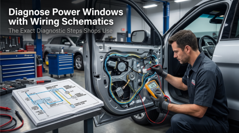
Diagnose Power Windows with Wiring Schematics before that stuck glass turns into soaked seats, theft exposure, or an inspection failure. Guessing at motors and switches gets expensive fast when the real fault is often a blown fuse, a broken wire, or a weak ground.
Start with the vehicle-specific schematic, verify fuse and relay power, then trace voltage and ground at the switch and motor before removing parts. This proves where the circuit fails, rather than replacing good components.
This guide covers schematic reading, polarity reversal, power and ground checks, switch testing, relay checks, motor confirmation, and common wiring breaks. Follow it in order, and the fault usually shows itself without drama.
Diagnose Power Windows with Wiring Schematics: What Most Techs Get Wrong

Most DIYers swap motors or switches without ever opening a schematic. A wiring diagram tells you where the current should be before you assume what failed. This section covers the full diagnosis workflow, component by component, using your vehicle’s factory wiring schematics as the map.
Understanding the power path from battery to motor is the only way to avoid replacing parts that were never broken. Every step below references a specific point you will locate on your schematic first.
Step 1: Get the Right Schematic Before Touching a Wire
Grabbing a generic diagram wastes time and causes errors. Your vehicle’s factory wiring schematic includes vehicle-specific wire colors, connector locations, and relay types that differ by year, trim, and body style.
- Locate the power window circuit in your OEM factory service manual or a trusted OEM-sourced database
- Note the fuse number, amperage rating, and fuse box location shown in the schematic
- Identify the relay. Some vehicles integrate it into the body control module (BCM), others use a standalone relay in the underhood fuse box
- Mark the window motor connector pin numbers and wire colors for both the up and down circuits
- Flag the ground reference points listed in the schematic. These are your voltage test baselines
One area shops repeatedly overlook is the door-to-body wiring harness. Just like when you read auto wiring diagrams to trace shorts, the door flex area is a prime location for broken conductors that show zero visible damage externally.
|
Schematic Component |
What to Note First |
|
Fuse number and amperage |
Confirms the correct fuse to test |
|
Relay pin layout |
Needed for relay bypass test |
|
Motor connector pinout |
Identifies power and ground wires |
|
Ground points |
Required for the voltage drop test |
|
Wire color codes |
Prevents probing the wrong terminal |
Step 2: Confirm Fuse and Relay Don’t Skip This
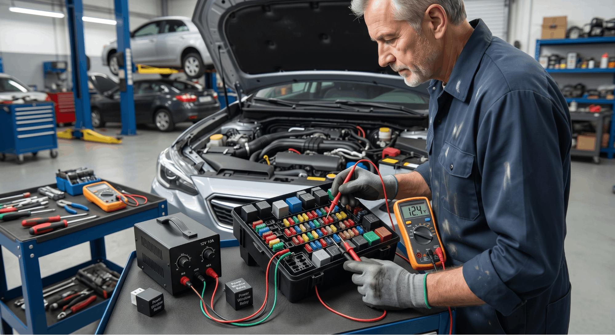
Fuse and relay faults account for nearly 40% of power window failures. Before opening any door panel, spend two minutes here.
Fuse check:
- With the ignition ON, use a multimeter set to DC volts and probe both sides of the window fuse
- A good fuse shows 12V on both terminals. If one side reads 0V, the fuse is blown
- Replace with the exact amperage listed in the schematic, never upsize
Relay check:
For vehicles with a dedicated power window relay, follow the relay testing procedures manual pinouts process:
- Locate the relay on your wiring schematic and remove it from the box
- Use a 12V source and jumper wire to energize terminals 85 and 86. You should hear an audible click
- With a multimeter, confirm continuity between terminals 30 and 87 when the relay is energized
- No click or no continuity means a failed relay replace and retest before going further
|
Relay Terminal |
Function |
|
85 |
Ground side of coil |
|
86 |
Power side of the coil |
|
30 |
Common (input power) |
|
87 |
Normally open (output to circuit) |
|
87a |
Normally closed (not used in most window circuits) |
Step 3: Trace Voltage from Switch to Motor Connector
This is where the schematic becomes your most valuable tool. The power window circuit supplies 12V to one motor terminal and grounds the other; polarity reverses to change direction.
At the switch connector:
- Backprobe the switch connector with ignition ON
- Confirm 12V battery voltage on the feed terminal. This is labeled on your wiring schematic
- Confirm a clean ground on the ground terminal resistance must be under 0.5 ohms
Checking voltage at the motor connector:
- Disconnect the motor connector
- Set your multimeter to DC volts
- Probe both terminals with ignition ON and switch pressed UP. One terminal should show +12V, and the other should show 0V (ground reference)
- Press switch DOWN polarity should reverse, showing 0V on the first terminal and +12V on the second
- If no voltage change occurs, the problem is in the wiring between the switch and the motor, or in the switch itself
Applying multimeter sensor testing via workshop manuals, discipline here keeps readings accurate. Always backprobe without piercing insulation when possible.
Step 4: Test the Switch with Schematic Pin Mapping
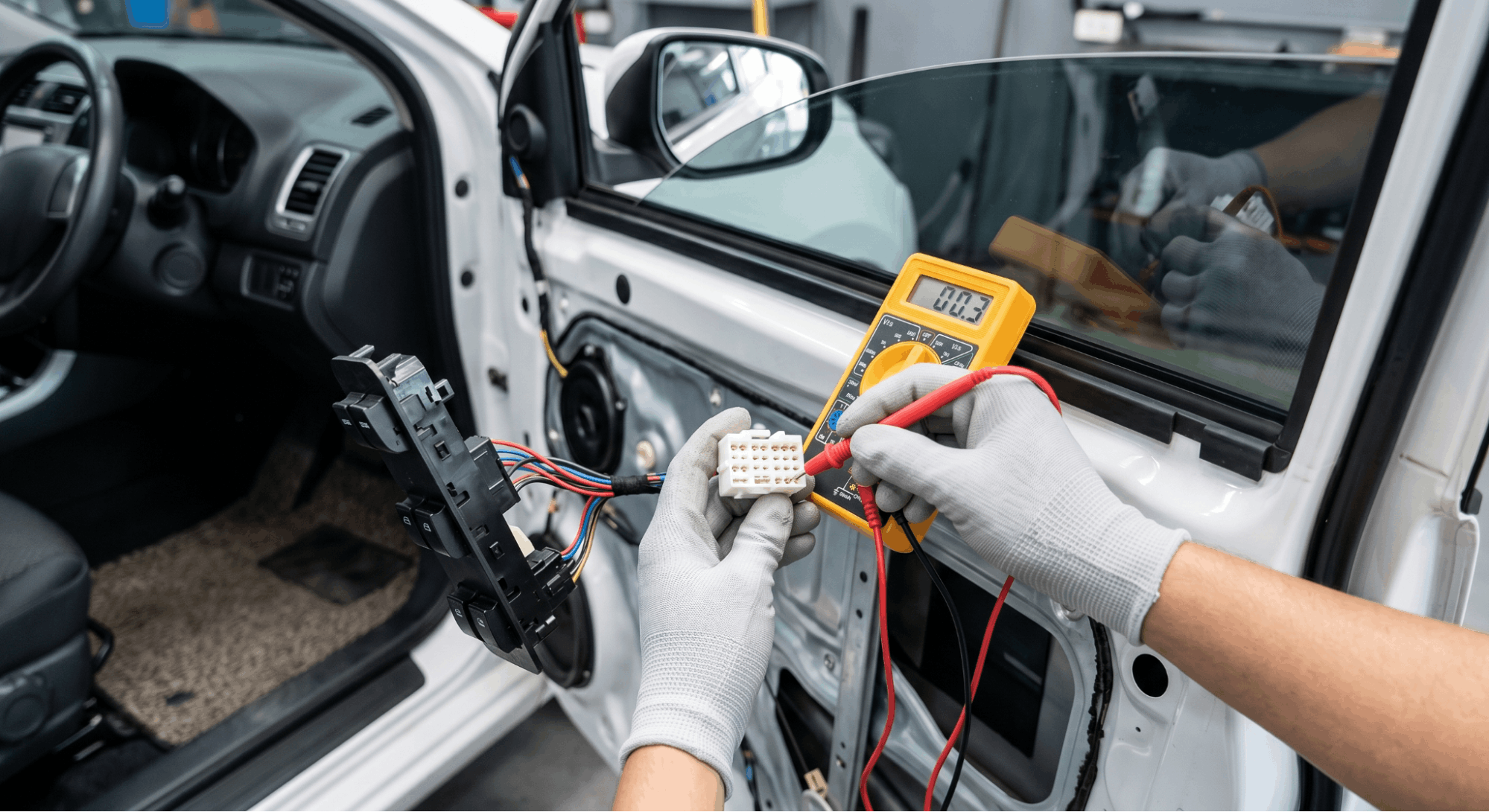
A faulty power window switch is a common culprit, especially on driver’s door master switches that endure the most use. Dirty internal contacts or moisture intrusion can cause intermittent or total failure.
- Reference your schematic for the switch connector pinout. Each pin number corresponds to a specific circuit
- With the switch disconnected, use a multimeter in resistance/continuity mode
- Press UP on the switch to confirm continuity between the correct pin pair shown in the wiring diagram
- Press DOWN the continuity pair should change to reflect polarity reversal
- A switch that shows no continuity change in either direction is faulty
Signs pointing to switch failure specifically:
- The driver’s window works, but the passenger windows controlled from the master switch do not
- The window works from the local door switch, but not from the master switch
- An intermittent operation that clears temporarily after pressing the switch repeatedly
Important: On vehicles with a BCM-controlled window circuit, the switch provides a signal input rather than supplying power to the motor directly. In these systems, test the signal voltage at the BCM connector pins as defined in your factory schematic. Do not expect 12V at the motor side from the switch alone.
Step 5: Identify and Test Ground Faults in the Circuit
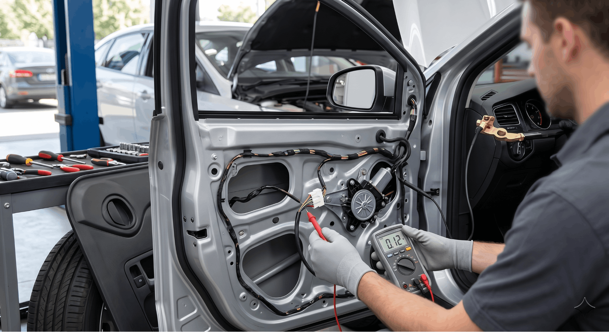
Ground faults are underdiagnosed in power window failures. A high-resistance ground will prevent the motor from running even when the switch and fuse test fine.
Use the hidden chassis ground points manually to locate every ground reference point identified in your schematic for the window circuit. Then:
- With the circuit active (ignition ON, switch pressed), perform a voltage drop test
- Place the multimeter negative lead on the battery negative terminal, positive lead on the motor ground terminal
- Acceptable voltage drop: under 0.1V on the ground side
- A reading above 0.3V confirms a high-resistance ground trace back to the chassis connection on your wiring schematic, and clean or repair it
Common ground failure locations:
- Door hinge ground strap (corroded or loose)
- Body-to-chassis ground bolt behind the kick panel
- Motor internal ground (tested by direct battery feed, see Step 6)
Step 6: Direct-Feed the Motor to Confirm Motor Health
If voltage testing confirms the circuit is delivering correct power and a solid ground to the motor connector, but the window still does not move, the motor is the likely failure.
Direct battery feed test:
- Disconnect the motor connector
- Run two jumper wires directly from the vehicle battery positive to one motor terminal, negative to the other
- The window should move in one direction
- Swap the jumper wires (reverse polarity), and the window should move in the opposite direction
- No movement in either direction confirms motor failure
A motor that hums but does not move points to a mechanical regulator failure rather than an electrical one. Inspect the regulator for broken guide wheels or stripped gears before condemning the motor.
If you suspect related drain issues from a faulty motor or switch keeping circuits partially active, review parasitic drains with factory schematics to rule out a background current draw after repairs.
Common Power Window Fault Reference Table
|
Symptom |
Most Likely Cause |
Schematic Test Point |
|
No operation, all windows |
Blown main fuse or relay |
Fuse box, relay socket |
|
No operation, one window |
Local switch or motor |
Motor connector, switch pins |
|
Works one direction only |
Switch contact or BCM output |
Switch pin continuity |
|
Slow or weak movement |
High-resistance ground or weak motor |
Voltage drop at motor ground |
|
Intermittent operation |
Door harness flex break |
Harness between the door and the body |
|
Works from the door switch, not the master |
Master switch internal contact |
Master switch continuity test |
Conclusion
Diagnosing power windows without a wiring schematic is like navigating without a map; you will eventually arrive, but you will waste time and money getting there.
Pulling the correct factory schematic, confirming fuse and relay health, tracing voltage along the wiring step by step, and direct-feeding the motor are not optional steps.
They are the exact sequence that eliminates guesswork and identifies the real fault the first time. Keep your multimeter calibrated, your ground connections clean, and your diagnostic sequence tied to the schematic in front of you.
That is how experienced techs close a power window job in under an hour.
Frequently Asked Questions
Yes, and this is more common than most people expect. The power window motor relies on a clean ground for current to flow in both directions.
A high-resistance or intermittent ground connection can allow the motor to operate in one direction, usually down, since gravity assists the glass but fails in the other. Always perform a voltage drop test on the wiring ground path before replacing the motor or switch.
Use your vehicle’s factory schematic to locate the exact chassis ground point for the window circuit, then test the resistance from that point to the battery negative terminal.
A reading above 0.3V means the ground needs repair before any other diagnosis makes sense.
This almost always points to a broken wire inside the door-to-body wiring harness. The harness flexes with every door opening and closing, and individual conductors eventually fracture internally without showing visible damage to the outer jacket.
The break creates an intermittent open circuit that only makes or loses contact at a specific door angle. To confirm, wiggle the harness near the hinge area while operating the window switch.
If the window flickers or suddenly works, you have found the fault zone. Use your wiring schematic to identify which conductors run through that harness segment, then test continuity on each one.
On modern vehicles, the master power window switch sends a signal input to the BCM, which then controls the actual power to the motor.
If the switch tests good, correct continuity on all pin pairs per the wiring schematic, but the motor still receives no voltage, the BCM output circuit is suspect.
Backprobe the BCM output connector using the pin assignments in the factory schematic and check for 12V at the motor output pin when the switch is pressed.
If the BCM shows no output despite a valid switch input, the BCM is at fault. Do not replace a BCM based on symptoms alone; confirm with schematic-referenced voltage testing first.
Most power window circuits use a 20- to 30-amp fuse, but the exact rating is specified in your vehicle’s factory wiring schematic and should never be assumed. Installing a higher-amperage fuse to stop repeated blowing does not fix the problem.
It removes circuit protection, allowing wiring, switches, and motors to carry dangerous levels of current.
A repeatedly blown fuse almost always signals a short circuit in the wiring harness, a sticking motor drawing excessive current, or a failed switch with internal shorting.
Always identify the root cause of fuse failure before replacement, and always restore the manufacturer-specified fuse amperage.
Using a generic or universal wiring schematic for power window diagnosis is risky and often inaccurate. Wire colors, connector pin assignments, relay locations, and BCM integration vary significantly across makes, model years, and trim levels.
A wire shown as red on a generic diagram could be green/white on your actual vehicle. Probing the wrong pin based on an inaccurate schematic can cause a short or damage the BCM.
For accurate diagnosis, use your vehicle’s factory service manual, a manufacturer-licensed database, or a verified OEM wiring diagram specific to your exact VIN. This is the only way to ensure every test point you probe is the correct one.