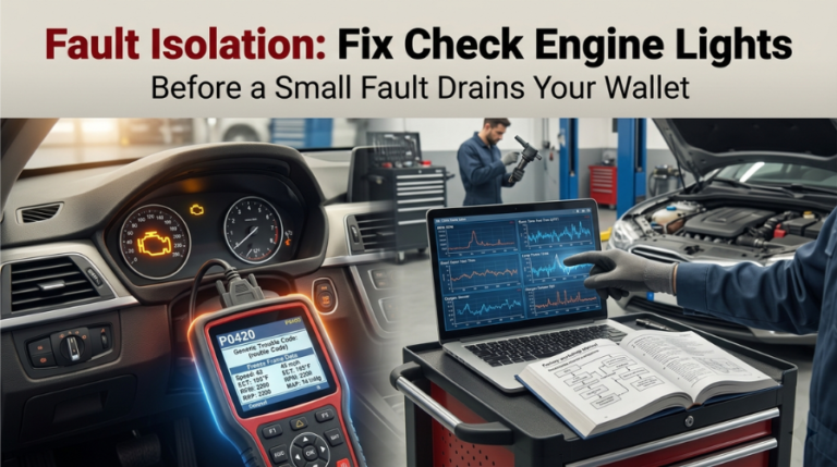
A fault left untraced, an engine light dismissed without proper isolation, and no clear plan to fix things the right way, that combination turns a $90 sensor job into a $900 mistake. Most drivers panic or blindly clear the code, and the light returns within days.
Fixing a check engine light requires a specific sequence: read DTCs, save freeze frame data, isolate the root cause, and confirm with live data. A solid light is non-urgent, but a flashing light indicates a severe misfire that risks damage to the catalytic converter.
This guide breaks down every step of that sequence, so your diagnosis hits the root cause the first time, not the third.
Fault Isolation: Fix Check Engine Lights Right — The Method Professionals Actually Follow
Most drivers pull one code, replace the part it names, and watch the light return within two drive cycles. That is not fault isolation, that is expensive guessing. Real isolation means tracing a
Diagnostic Trouble Code (DTC) to the system, ruling out downstream effects, and confirming the actual failure with live sensor data before any part is ordered.
Step 1: Pull Every Code — Not Just the First One
Before anything else, connect your OBD-II scanner to the diagnostic port under the driver’s side dashboard. Turn the ignition to “ON” without starting the engine, then read all stored and pending DTCs. Write down every single code, do not stop at the first one.
The letter prefix tells you the affected system immediately:
|
Code Prefix |
System Affected |
Common Examples |
|
P |
Powertrain (engine, fuel, transmission) |
P0171, P0300, P0420 |
|
B |
Body control (airbags, interior) |
B1000, B2799 |
|
C |
Chassis (ABS, suspension, brakes) |
C0035, C0121 |
|
U |
Network/communication |
U0100, U0401 |
When multiple codes appear together, one is almost always the primary fault that triggers the others. Address the earliest-triggered or most foundational code first.
Replacing a downstream component while the upstream fault remains active guarantees the code returns. The Check Engine Light step-by-step diagnostic using factory repair manuals resource outlines this prioritization process precisely.
Step 2: Save Freeze Frame Data Before Clearing Anything

Freeze-frame data is the ECU’s snapshot of engine conditions at the exact moment the check engine light triggered. It records RPM, vehicle speed, coolant temperature, throttle position, engine load percentage, and fuel trim values, all captured at the fault instant.
Never clear codes before saving this data. Clearing resets all readiness monitors and permanently erases freeze frame, which is often your single most valuable diagnostic clue.
Screenshot it, write it down, or export it from your scanner app. Then cross-reference these key parameters:
- Engine Load %: High load at fault time suggests a mechanical or fuel delivery issue
- Coolant Temperature: Cold-start faults point to sensor or warm-up circuit problems
- Short-Term Fuel Trim: Values above +10% signal an active lean condition
- RPM at Fault: Idle-only faults behave very differently from cruise-speed faults
A lean code triggered at idle versus one triggered at highway speed narrows the possible causes by more than half before any physical inspection begins.
Step 3: Isolate the Root Fault — Not the Symptom Code
This is the critical step most DIYers skip. An OBD-II code identifies the affected circuit or system, not the failed component. P0420 flags catalytic converter efficiency below threshold, but a failing converter is rarely the initiating cause.
Common fault isolation traps by code:
- P0420: Often caused by misfires, O2 sensor failure, or an exhaust leak — not a bad catalyst
- P0171 (Lean Bank 1): Frequently traced to a vacuum leak or weak fuel pump — not just the MAF sensor
- P0300 (Random Misfire): Can originate from low fuel pressure or carbon-fouled injectors — not only spark plugs
Use OBD-II manual diagnostic flowcharts to walk each code through its proper decision tree. This prevents condemning a healthy component based on a misread symptom code.
Before touching any sensor, inspect the wiring harness and connector at the ECU. A corroded or damaged pin can cause the same fault code as a dead sensor, at a fraction of the cost of a repair. The ECU pinout charts, explained in the diagnostics guide, map every connector for the most common engine configurations.
Step 4: Confirm the Fault With Live Data — Then Order Parts
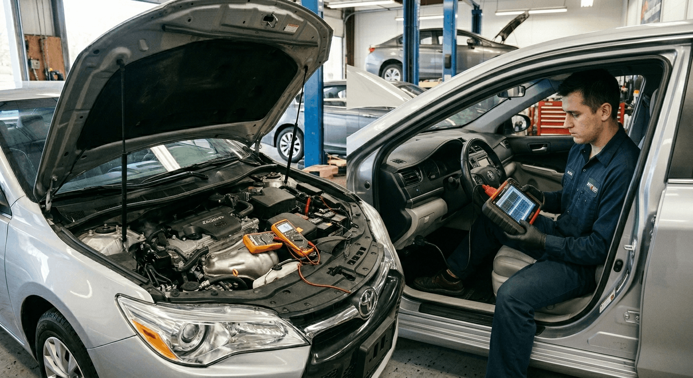
Live data is real-time proof that confirms or eliminates your working diagnosis. With the scanner connected and the engine running, compare sensor output against factory specification ranges for your exact vehicle.
Focus on these live data parameters during fault confirmation:
- STFT/LTFT (Fuel Trims): Long-term fuel trim above +10% at idle confirms the ECU is compensating for a lean condition
- O2 Sensor Switching: A flat or slow-switching signal indicates a failing sensor or downstream exhaust problem
- Misfire Counters Per Cylinder: Isolates an active misfire to a specific cylinder — guiding coil, plug, or injector testing
- MAF g/s at Idle: Deviations from displacement-based spec suggest sensor contamination or air intake leaks
Pull factory spec ranges for your specific engine from your vehicle’s service manual using the VIN. The factory service manual PDF by VIN resource provides the exact thresholds for each model year and engine variant, not generic estimates.
Step 5: Fix Right, Then Verify Through a Full Drive Cycle
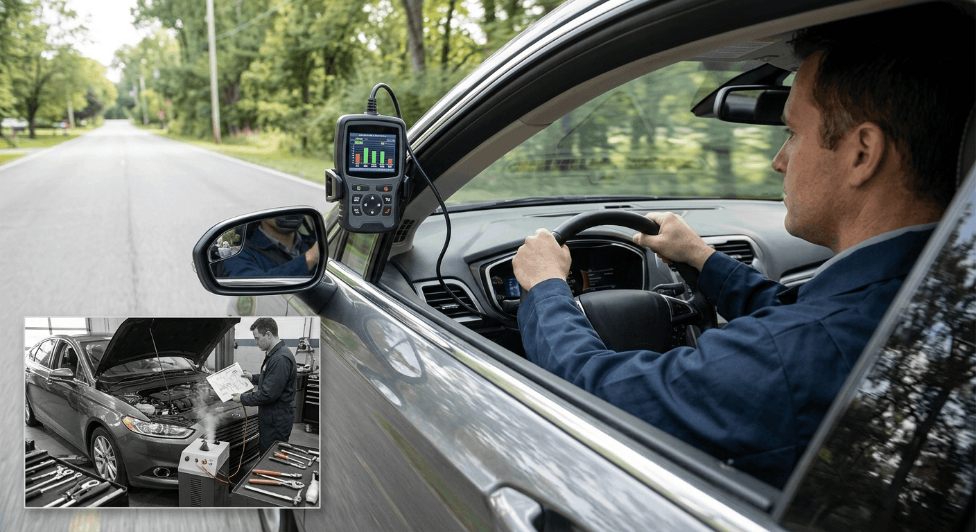
After completing the repair, clear the stored DTC and complete a proper OBD-II drive cycle for the affected monitor. Simply clearing the code and driving around the block isn’t verification—it’s hope.
Drive cycles require specific conditions: cold start, idle period, steady cruise speed, deceleration, and sometimes a set engine temperature range.
Post-repair verification checklist:
- Clear the DTC and freeze frame after the confirmed repair
- Complete the full drive cycle for the affected monitor group
- Reconnect the scanner and check the I/M readiness monitor status
- Confirm all monitors show “Ready” or “Complete.”
- Verify zero new stored or pending codes after the drive cycle
If the code returns after this process, do not repeat the same repair. Re-evaluate using fresh live data. Comparing OEM vs. aftermarket repair manual accuracy for DIY diagnostics helps confirm whether the reference source you used contains the correct diagnostic tree for your application.
Conclusion
Fault isolation is not one action it is five sequential steps that each build on the last. The check engine light is only the starting signal. Reading every DTC, capturing a freeze frame before clearing anything, tracing to the upstream fault, confirming with live data, and verifying through a proper drive cycle are what produce a lasting fix.
Every shortcut in that sequence increases the chance the light will return, and the repair bill will grow. Work the process correctly once, and the engine stays right.
Frequently Asked Questions
A flashing check engine light signals an active, repeated misfire, not a pending or stored fault. Every driving mile in this condition pushes raw, unburned fuel directly into the catalytic converter, raising its internal temperature well beyond the designed operating range.
Sustained exposure destroys the substrate inside the converter, turning a straightforward ignition coil or spark plug repair into a catalytic converter replacement that typically costs between $900 and $2,500, depending on the vehicle.
The safest response is to immediately reduce engine load, find a safe stopping point, shut the engine off, and arrange a tow. No destination is worth that cost difference.
OBD-II codes identify affected circuits and systems, not the specific failed part. A P0138 code, for example, flags abnormally high voltage at a specific oxygen sensor, but elevated voltage at that sensor can result from a rich-running fuel condition rather than a faulty sensor itself.
Replacing the sensor without investigating the fuel trims and injector data leaves the rich condition active, and the ECU logs the same code again within one to two drive cycles.
Accurate fault isolation using live data before any part purchase is the only method that prevents this pattern. The code tells you where to look, not what to buy.
A pending DTC is the system’s initial detection of an out-of-range reading that appeared once but has not yet repeated enough times to trigger the check engine light. A stored or confirmed
DTC has been detected on at least 2 consecutive drive cycles, during which the engine light illuminates. Pending codes matter significantly during diagnosis because they often represent the initiating fault that later generates confirmed, downstream codes.
Experienced technicians review pending codes during every scan because pending codes often reveal root system failures before they escalate into a full set of confirmed fault codes with more complex diagnostic paths.
Disconnecting the battery clears stored DTCs and turns off the check engine light, but it resolves nothing mechanically. The OBD-II system detects the same underlying fault during the very next drive cycle and logs the code again.
Beyond that, disconnecting the battery resets all readiness monitors to “Not Ready,” which causes an immediate failure at an emissions inspection even when no fault codes are currently stored. The monitors require several complete drive cycles to return to “Ready” status.
Additionally, erasing freeze-frame data during battery disconnection eliminates the most useful diagnostic snapshot, making subsequent diagnosis harder and slower.
Generic OBD-II scanners read standardized P0 codes reliably across virtually all makes and model years since 1996. Manufacturer-specific codes identified by the “1” as the second digit, such as P1XXX, require either a professional-grade enhanced scan tool or a brand-validated diagnostic interface.
A generic scanner may display the code number without a meaningful description, or it may misidentify the affected system entirely. For accurate fault isolation on these proprietary codes, cross-reference with an OEM factory service manual specific to your vehicle’s make and model year.
Using a validated OEM reference ensures the diagnostic flowchart you follow was designed for that exact engine management system configuration.