
Hidden Chassis Ground Points in the Manual often go unnoticed during basic inspections, yet they can quietly trigger widespread electrical failures. A single corroded connection can cascade into sensor glitches, starting issues, and unpredictable faults that are hard to trace.
The fastest solution is to use your factory service manual to locate every chassis ground point with precise diagrams and reference numbers.
This guide explains how to read wiring diagrams, identify ground labels like G100 series points, and physically trace them on your vehicle. You will also learn how to test each connection to prevent recurring electrical issues.
Find Hidden Chassis Ground Points via Manual: The Insider Method Most Techs Overlook

Most electrical failures trace back to a single overlooked ground connection. Factory service manuals contain ground distribution charts, splice locations, and torque specs that forums and YouTube videos simply do not provide.
Learning to read these pages correctly puts you ahead of most professional technicians and dramatically reduces diagnostic time.
Why Factory Manuals Hold Ground Data, Others Miss
Before picking up a multimeter, knowing what the manual actually says saves more time than any shortcut.
Factory manuals dedicate entire sections to ground distribution, sometimes labeled “Ground Point Locations” or “Body Ground Distribution.” These pages list every chassis ground point, including a diagram reference, wire color, and connector code.
Most technicians skip straight to circuit diagrams and miss this section completely.
- Ground distribution charts display all negative return paths in a single view
- Diagram reference codes link each ground to its specific circuit number
- Wire color codes match factory harness colors for fast visual tracing
- Connector IDs pinpoint the exact splice location without guessing
Pairing the manual’s ground section with wiring diagrams to trace shorts gives you a complete picture of how current flows and exactly where it breaks down.
How to Read Ground Distribution Pages in Any Manual

The ground distribution section is laid out differently across vehicle brands, but the logic stays consistent once you understand the structure.
Most factory manuals organize ground points by zone — engine bay, cabin, trunk, and underbody. Each zone lists the chassis mounting location, the circuits it serves, and the required wire gauge.
Start from the symptom, not the schematic.
- Identify the faulty circuit using your scan tool or symptom description
- Cross-reference that circuit number in the ground distribution index
- Locate the zone and diagram reference for that ground point
- Use the diagram reference to find the physical location on the chassis
If you need your factory document first, finding your factory service manual PDF by VIN is the critical first step before any of this process works.
Hidden Ground Point Locations by Vehicle Zone

Hidden ground points are rarely where you expect them. Manufacturers tuck connections under trim panels, behind splash shields, and inside firewall grommets to protect them from moisture and road debris.
Knowing the common zones significantly reduces your search time and prevents unnecessary disassembly.
|
Vehicle Zone |
Common Hidden Ground Location |
Typical Circuits Served |
|
Engine Bay |
Behind the intake manifold bracket |
ECU, injectors, sensors |
|
Firewall |
Inside grommet channel, driver side |
Body control module, fuse block |
|
Under Dash |
Behind the kick panel trim, left side |
Instrument cluster, HVAC |
|
B-Pillar |
Under door seal trim |
Door modules, airbag sensors |
|
Rear Cargo |
Under the trunk carpet near the tail light |
Tail lamps, fuel pump |
|
Underbody |
Frame rail, rear axle area |
Fuel system, trailer connector |
Each of these points connects to multiple circuits. One corroded connection here causes failures across several unrelated systems simultaneously.
Step-by-Step: Locate and Test a Chassis Ground Point
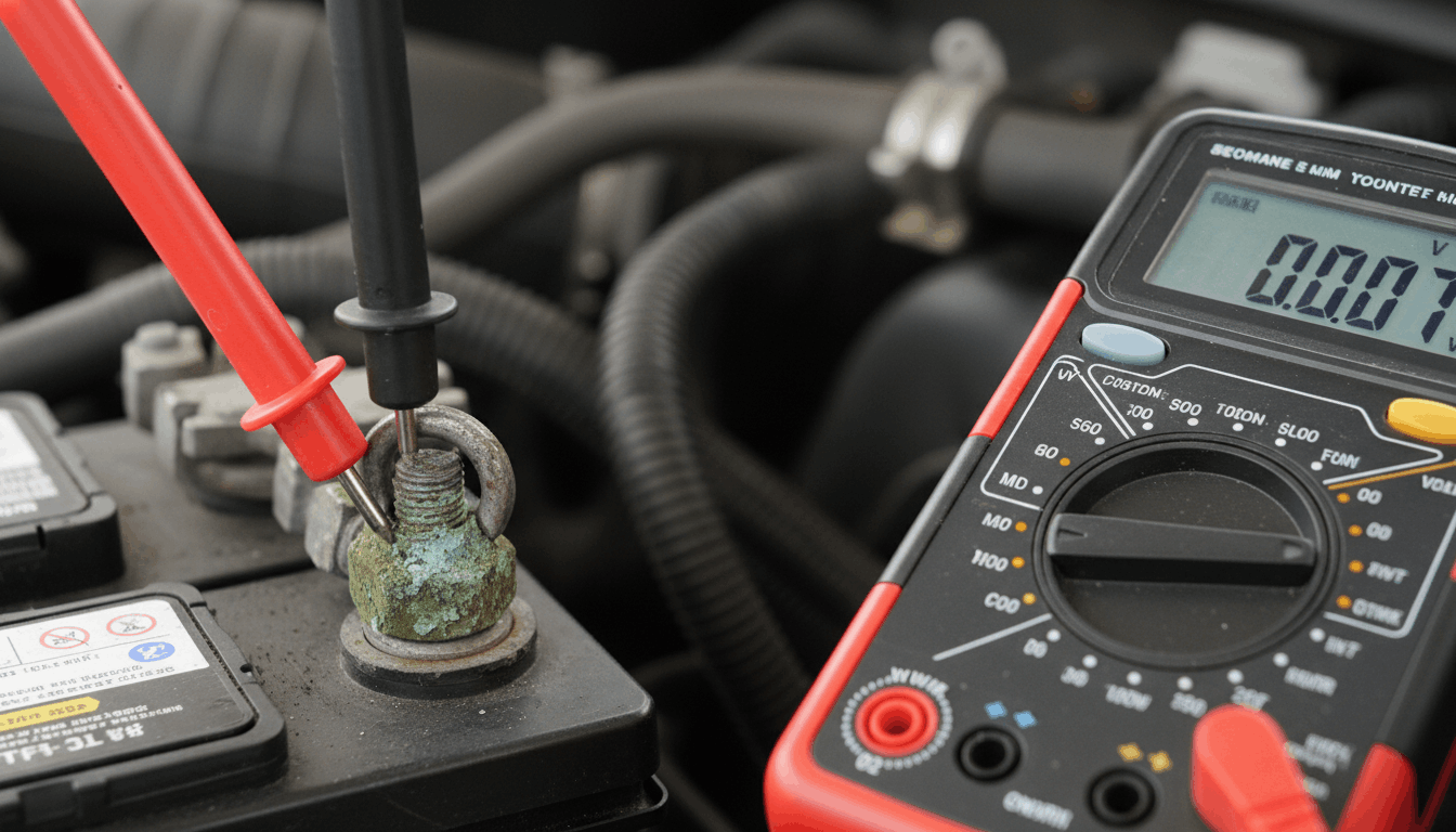
Once the manual directs you to a ground point, the physical inspection and testing process follows a fixed sequence that works on any platform.
Rushing through these steps creates missed faults that return within weeks.
Step 1: Navigate to the Physical Point. Use the chassis diagram in your manual to locate the exact mounting location. Look for a bolt, stud, or ring terminal fastened directly to unpainted bare metal.
Step 2: Inspect. Visually check for white or green corrosion around the terminal. Corrosion increases resistance and causes a voltage drop even when the connection looks mechanically tight.
Step 3: Test Voltage Drop Set your multimeter to DC millivolts. Connect the negative lead to the battery negative and the positive lead to the ground point stud. Load the circuit by cranking the engine or activating the relevant system. Any reading above 200 mV indicates a failing ground.
For a complete look at this measurement technique, multimeter sensor testing via workshop manuals covers the exact procedure with practical live examples.
Step 4: Clean and Re-Torque Remove the terminal, clean both contact surfaces with a wire brush, apply dielectric grease, and re-torque to the specification listed in your manual. Most chassis ground bolts require between 8 and 12 Nm.
Step 5: Re-Test and Verify. Run the voltage drop test again immediately after reassembly. Confirm the reading drops below 100mV before closing panels or moving to the next point.
Ground Point Failures and What They Trigger
A single failing chassis ground point triggers cascading faults that appear completely unrelated on a scan tool. Understanding the cause-and-effect relationship prevents misdiagnosis and wasted parts.
These are the most common failure patterns tied to specific zones:
- Corroded engine bay ground: Random misfires, injector timing faults, rough idle under load
- Firewall ground failure: BCM communication errors, gauge cluster dropouts, dead accessories
- Under-dash ground issue: HVAC blower failure, interior lighting faults, cluster dimming
- Rear ground corrosion: Fuel pump voltage drop, intermittent tail light codes, trailer faults
If your scan tool shows ECU-related faults alongside these symptoms, reviewing ECU pinout charts for diagnostics helps confirm whether the root cause is a ground issue or an internal module fault.
Intermittent issues that cause battery drain often trace back directly to a hidden ground-point problem. Cross-checking parasitic drains against factory schematics and ground testing keeps the diagnostic process efficient and focused.
When to Add Supplemental Ground Straps

Some vehicles benefit from added chassis ground straps, especially high-mileage platforms or modified builds. Your factory manual shows the original strap routing, which tells you where supplemental connections make the most sense on your specific vehicle.
Adding a ground strap without understanding the original layout creates ground loops that introduce entirely new faults.
- Match the wire gauge to the original factory specification in the manual
- Terminate at bare metal only, never at painted or coated surfaces
- Follow the original ground point layout shown in the manual as your baseline
- Never route supplemental grounds across moving or heat-generating components
Conclusion
Tracking down hidden chassis ground points through your factory manual is one of the most valuable diagnostic skills you can build. The manual tells you exactly where every ground point lives, what circuits it serves, and how to verify its condition without guessing.
Start with the ground distribution section, cross-reference your symptom to the correct circuit number, then follow the five-step test procedure. That sequence alone resolves the majority of electrical faults that leave most shops stumped for days.
Frequently Asked Questions
Yes, and it happens far more often than most people expect. The starter motor and ignition system both rely on solid chassis ground connections to complete their return circuits.
A corroded or loose ground point at the engine block or firewall prevents enough current from flowing to crank the engine properly. The battery may test at full charge, the alternator may output correctly, but without a solid negative return path, the system simply cannot complete the circuit.
Always test ground integrity using a voltage drop test before condemning the starter or battery in a no-start situation. The test takes under five minutes and reveals the fault immediately.
Most modern vehicles carry between 15 and 40 individual chassis ground points, depending on electrical complexity. Trucks and SUVs equipped with trailer wiring, advanced driver-assist systems, and multiple body modules typically cost more.
Entry-level vehicles with simpler electrical layouts use fewer. Your factory manual lists every single point inside the ground distribution section. High-end European vehicles sometimes feature 50 or more discrete ground locations spread across the body, engine, and infotainment zones.
Knowing the total count for your specific platform allows you to perform a systematic inspection rather than spot-checking random locations and hoping you find the right one.
A chassis ground point is considered faulty when the voltage drop reading exceeds 200 millivolts under a real electrical load. Ideal ground connections measure below 50mV during normal circuit operation.
Readings between 100 mV and 200 mV indicate early-stage corrosion that will worsen over time. Anything above 200mV requires immediate cleaning and re-termination before it takes down additional systems.
Always test under actual load rather than with a static continuity check, because resistance only becomes measurable when current flows through the connection. Your manual lists the correct load specification for each circuit, so you apply the correct current during testing.
Factory manuals document only the original manufacturer’s ground points installed in the vehicle at the time of production. They do not cover aftermarket additions, such as audio upgrades, LED lighting kits, or dealer-installed tow packages, added after delivery.
For aftermarket accessories, follow the accessory manufacturer’s wiring guide and tie into existing chassis ground studs shown in the factory manual. Improper aftermarket grounding is a leading cause of electrical interference, module communication faults, and accelerated corrosion at factory points from overloaded connections.
Always verify the stud’s current capacity rating before adding additional circuits to an existing ground location on the chassis.
Ground point corrosion accelerates on vehicles exposed to road salt, high humidity, or coastal air year-round. Dissimilar metals at the terminal and chassis contact surface create galvanic corrosion that eats through the connection over time.
Factory manuals sometimes specify dielectric grease or corrosion-resistant hardware at specific points for exactly this reason. Vehicles operated in cold climates with frequent exposure to de-icing salt should have their chassis ground points inspected every 2 to 3 years as part of scheduled maintenance.
Sealing the terminal properly after cleaning significantly extends the lifespan of the connection and prevents repeat failures at the same location during the next inspection cycle.