Your wiper motor, linkage, and assembly, along with the diagrams that connect them, are not just a mechanic’s concern. When the wipers quit mid-storm, and you can’t see ten feet ahead, it becomes your problem very much. A misread diagram or a skipped part during reassembly can cost you visibility, safety, and real money.
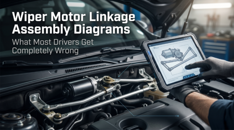
To fix it, you must read the assembly diagram correctly and understand every connection before starting. The wiper motor linkage assembly, or wiper transmission, transforms the motor’s high-speed rotation into synchronized, back-and-forth blade sweeps.
This article breaks down the full wiper motor linkage assembly diagram, its key components, common failure points, and how to use the diagram to diagnose and fix problems without guesswork.
Wiper Motor Linkage Assembly Diagrams: The Full Breakdown You Actually Need

Most guides either oversimplify this system or throw jargon at you without context. The wiper motor linkage assembly is a mechanical chain of parts, and every single link in that chain matters. Miss one component in the diagram and the whole system misbehaves. This section covers everything from the motor output shaft to the pivot arms and connecting rods, so you can read any diagram with confidence.
How the Wiper Motor and Linkage Work Together
Before touching the diagram, you need to understand the system’s logic. The wiper motor converts electrical energy into rotational motion. That spinning motion cannot go directly to the wiper blades because blades need to sweep back and forth, not spin in circles.
This is where the linkage assembly earns its name. It intercepts that circular motor output and converts it into a precise arc sweep. The diagram shows this conversion taking place through a series of mechanical components.
Here is what the full motion path looks like:
- The wiper motor spins via a worm gear inside the housing
- The worm gear connects to the crank arm mounted on the motor output shaft
- The crank arm pushes and pulls a series of connecting rods
- Those rods drive the pivot shafts on each side of the windshield
- The wiper arms mount onto those pivot shafts and sweep the glass
This chain is what the assembly diagram visually maps out. Understanding the path makes reading the diagram far easier.
Key Components Labeled in the Assembly Diagram
Every wiper motor linkage assembly diagram includes the same core parts, even if the layout differs by vehicle. Here is what each label means in the diagram:
|
Component |
Function |
|
Motor housing |
Holds the motor and mounts to the cowl panel |
|
Worm gear |
Transmits rotation from the motor to the crank arm |
|
Crank arm |
Converts rotary motion to linear rod movement |
|
Drive rod / primary link |
Transfers force from the crank arm to the pivot point |
|
Idler arm |
Secondary pivot that synchronizes blade movement |
|
Crossbar / drag link |
Connects both pivot shafts across the cowl |
|
Pivot shaft |
Anchors the wiper arm and allows arc movement |
|
Bushings |
Reduce friction at every pivot and joint |
|
Park switch |
Signals the motor to stop at the parked position |
|
Ball joints/sockets |
Allow angular movement between rods and arms |
These are the parts you will find labeled in any OEM or aftermarket assembly diagram. Knowing each one by name lets you cross-reference the diagram with the actual hardware under the cowl panel without confusion.
Reading a Wiper Linkage Assembly Diagram: Step by Step
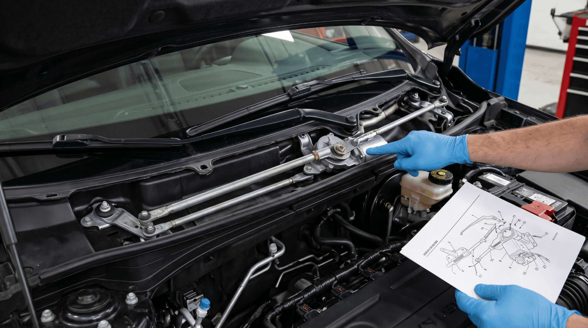
A lot of people pull up an exploded view or schematic diagram and immediately feel lost. The layout looks complex, but a logical reading order makes it simple. If you regularly work with exploded-view manual diagrams, you already know the format. Here is how to read a wiper linkage diagram specifically:
Step 1: Locate the motor first. The motor is the starting point of the entire system. It is usually the largest labeled component in the diagram, mounted near the firewall or cowl.
Step 2: Follow the crank arm. From the motor output shaft, a short crank arm extends outward. This is where rotational motion ends and linear motion begins.
Step 3: Trace the drive rod. The drive rod runs from the crank arm to the first pivot shaft. In the diagram, look for a long horizontal rod connecting these two points.
Step 4: Identify both pivot shafts. These are the anchor points for your driver-side and passenger-side wiper arms. They appear as vertical posts in most diagrams.
Step 5: Find the idler arm and crossbar. In tandem and opposed wiper systems, a crossbar connects the two sides. The idler arm sits on the passenger side and mirrors the motion from the driver’s side.
Step 6: Note all bushing locations. Bushings sit at every pivot and joint. In the diagram, they appear as small circles or sleeves inside the pivot points. These are the parts that wear out most often.
Tandem vs. Opposed Wiper Linkage Diagrams
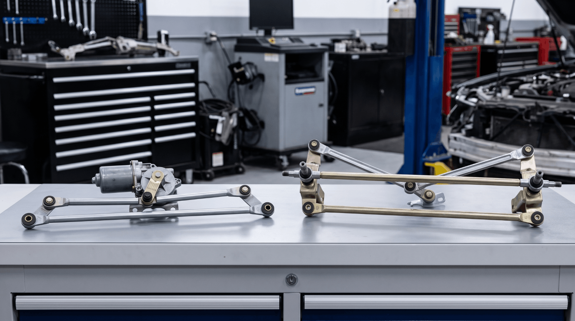
Not all vehicles use the same linkage design, and the diagram layout changes significantly depending on the system type.
Tandem linkage systems move both wipers in the same direction simultaneously. The pivot points sit at the base of the windshield on the driver’s side and at the vehicle’s center. The diagram shows a simpler, more linear rod path.
Opposed linkage systems move wipers in opposite directions, sweeping a larger area of the windshield. Pivot points appear on both the driver’s and passenger’s sides of the diagram. The crossbar runs across the full width of the cowl, visible as a long horizontal rod in the schematic.
Knowing which type your vehicle uses tells you which diagram to reference. Using the wrong one leads to misidentified parts and incorrect reassembly.
Common Failure Points Visible in the Assembly Diagram
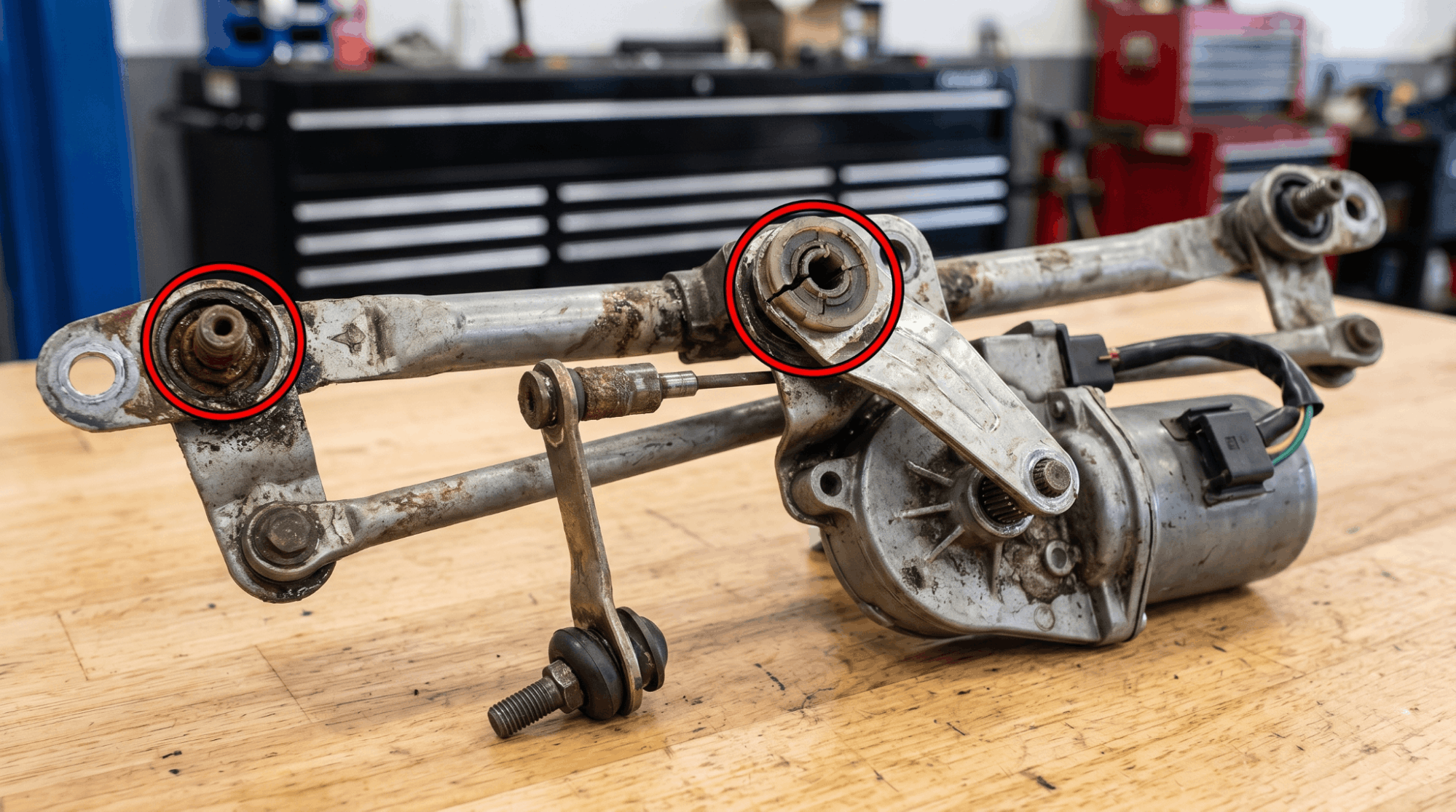
The assembly diagram is not just for installation. It is also a diagnostic tool. Once you know where the parts are, you know exactly where to look when something goes wrong.
Here are the most frequent failure points and their exact locations in the diagram:
- Worn plastic bushings at the crank arm and pivot shaft connections. These are the number one cause of wipers running but not moving. Dorman part numbers 49449 and 49452 are common replacements for popular GM vehicles.
- Loose ball joints at the connecting rod ends. If a rod pops off the crank arm, the motor runs silently while the wipers do nothing.
- Seized pivot shaft inside the linkage housing. This forces the motor to overwork and eventually burn out. Early signs include slower wiper speed and grinding noise.
- Stripped splines on the motor output shaft. If the crank arm spins freely without resistance, the spline is gone.
- Faulty park switch inside the motor. Wipers stop mid-sweep instead of returning to the bottom of the windshield.
Cross-referencing these failure points against your vehicle’s assembly diagram lets you isolate the exact part without blindly disassembling the whole system. This is also where access to a proper factory service manual PDF by VIN pays off, since OEM diagrams are specific to your exact trim and build year.
Reassembly Using the Diagram: What the Instructions Leave Out
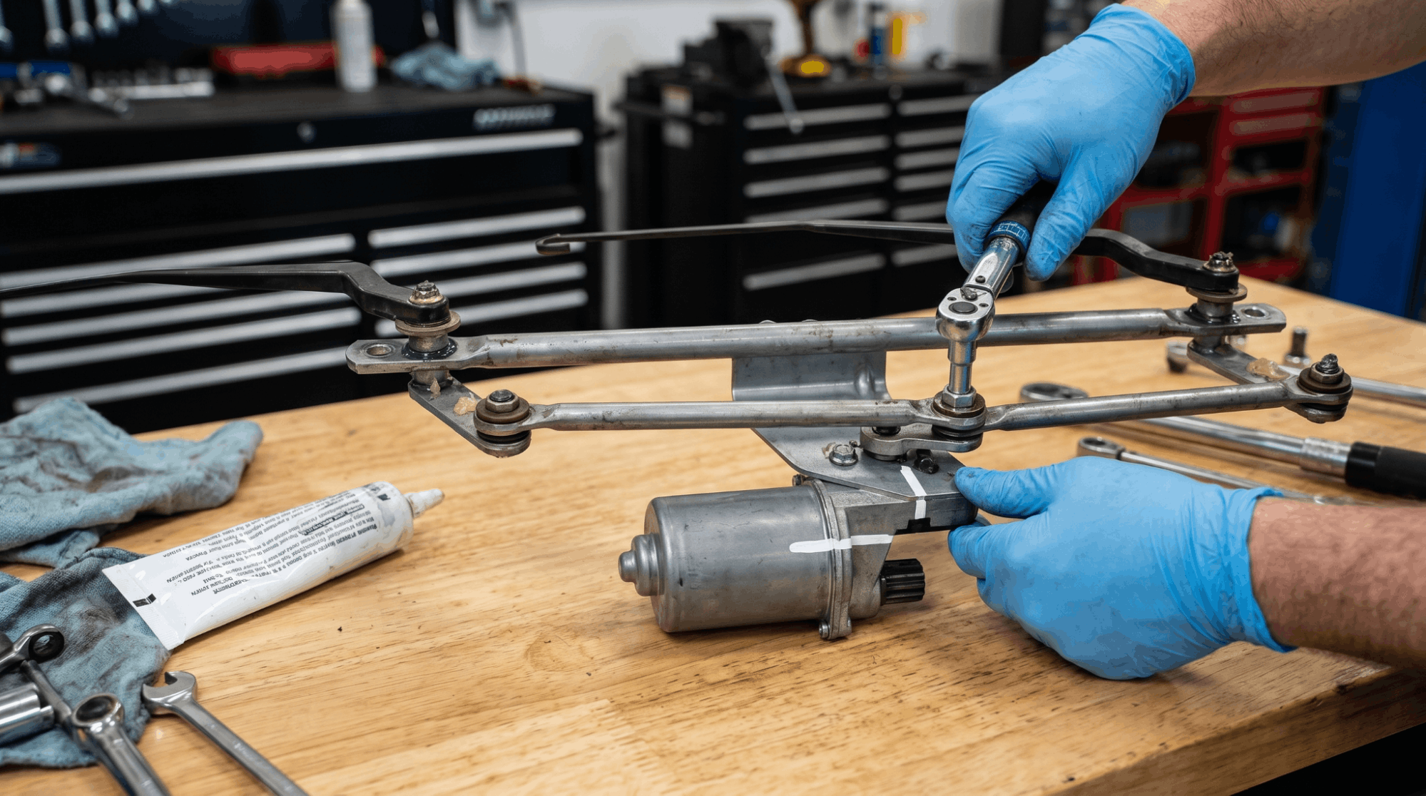
Reassembling a wiper linkage without following the diagram is how people end up with wipers that sweep in reverse or stop in the middle of the glass. The diagram tells you orientation, and orientation matters.
Torque values matter. Pivot arm nuts are typically torqued to 8-12 Nm. Over-tightening cracks the plastic pivot housing. Under-tightening causes the arm to rotate during operation.
Rod length is specific. The center-to-center measurement on the connecting rods usually falls between 9.5 and 11 inches. Installing a slightly different-length rod from an aftermarket kit will shift the sweep arc.
Mark the crank arm position before removal. If the crank arm is reinstalled at a different clock position on the motor shaft, the wipers will park incorrectly. Some mechanics use a paint marker to note the original alignment before disconnecting anything.
Lubricate every pivot point. The diagram marks all friction points. Use synthetic grease rated for high-temperature, high-cycle applications at every one of them. This significantly extends the bushing’s lifespan.
For deeper diagnostic work involving voltage checks at the motor connector, pairing the diagram with multimeter sensor testing via workshop manuals gives you the electrical picture alongside the mechanical one.
Finding the Right Assembly Diagram for Your Vehicle
Generic diagrams are useful for understanding the system, but OEM-specific schematics are what you need for real repairs. The part locations, rod lengths, and pivot configurations vary considerably across makes and models.
Your best sources for accurate wiper motor linkage assembly diagrams are:
- OEM workshop manuals sourced through your dealership or a trusted repository
- Alldata or Mitchell1 professional databases
- Interactive PDF workshop manuals that let you zoom, search by part number, and navigate by system. If you have not used one before, learning to navigate interactive PDF workshop manuals saves a lot of time compared to scanning through a static printout.
- Genuine OEM workshop manuals ensure the diagrams match your exact vehicle, not approximations from an aftermarket catalog.
Avoid relying solely on generic YouTube teardowns or forum posts for diagram accuracy. They are helpful for context but should not replace a vehicle-specific schematic.
Wiper Motor Linkage Assembly: Quick Diagnosis Table
|
Symptom |
Likely Cause in Diagram |
Part to Inspect |
|
Motor runs, wipers don’t move |
Disconnected ball joint or crank arm |
Drive rod, crank arm socket |
|
Wipers park in the wrong position |
Shifted crank arm on motor shaft |
Motor output shaft alignment |
|
One wiper stops, the other works |
Seized pivot shaft on that side |
Pivot shaft and bushing |
|
Wipers slow or grinding |
Worn bushing at multiple joints |
All bushing points in the diagram |
|
Wipers stop mid-sweep |
Faulty park switch inside the motor |
Park switch, motor assembly |
|
Blades are misaligned or uneven |
Incorrect rod length or misclocked arm |
Connecting rod length, arm position |
Conclusion
The wiper motor linkage assembly diagram is not just a parts map. It is the full story of how rotational force from a small electric motor turns into the back-and-forth sweep that keeps your windshield clear.
Every component in the diagram has a specific job, position, and failure mode.
Once you can read the diagram with confidence, diagnosing problems becomes faster, reassembly becomes accurate, and you stop replacing whole assemblies when a single bushing is the real culprit.
Use an OEM-specific diagram, match your vehicle’s linkage type, follow torque values, and lubricate every pivot point. That is the short version. The detail is all in the diagram itself.
Frequently Asked Questions
Yes, in many cases you can. The plastic bushings at the crank arm and pivot shaft joints are often sold separately.
Dorman and other aftermarket brands offer bushing kits specifically for popular models. The challenge is that some vehicles use pressed-in bushings that require an arbor press to seat correctly.
If the bushing has caused the drive rod to pop off repeatedly, replacing just the bushing is the right call before committing to a full assembly swap. Always confirm part compatibility with your vehicle’s year, make, and model before ordering.
It usually means the mechanical link between the motor and the blades has broken somewhere in the linkage.
The most common cause is a ball joint or plastic socket that has popped off the crank arm. The motor is still receiving power and spinning, but nothing is mechanically connected to it.
In some cases, a seized pivot shaft is creating so much resistance that the motor cannot push the linkage at all.
Either way, the diagnosis starts by removing the cowl cover and watching the crank arm while the motor runs.
The simplest way is to watch your wipers in operation. If both blades sweep in the same direction at the same time, you have a tandem system.
If they move toward and away from each other like a mirror image, it is an opposed system. You can also check your vehicle’s OEM diagram, which clearly shows the pivot point placement.
Opposed systems are more common on larger windshields because they clean a bigger surface area.
Yes, significantly. Rear wiper systems are much simpler. Most rear wipers use a single motor that connects directly to a single pivot shaft, without any secondary linkage, crossbar, or idler arm.
The rear wiper motor is usually mounted inside the tailgate or hatch door. The assembly diagram for a rear wiper consists of the motor, output shaft, and one pivot.
Front systems are far more complex because they need to synchronize two wiper arms across a wide windshield.
It depends on how “partial” the failure is. If one wiper arm has stopped moving entirely, most jurisdictions consider the vehicle unsafe for road use, particularly in rain or snow.
If both wipers move but park incorrectly or sweep at reduced speed, it is a developing failure that will likely worsen quickly.
A seized pivot shaft puts extra load on the motor, which shortens its life.
The practical answer is that you should not delay fixing a wiper linkage issue, as a full system failure at highway speed in bad weather poses a serious safety risk.