ECU Pinout Charts Explained for Diagnostics: What Most Technicians Get Wrong
ECUpinoutcharts get misread more often than you’d think, and the result is usually a misdiagnosis, a damaged connector, or a wiring job that creates more faults than it clears. Without understanding how these diagnostic reference maps actually work, even experienced technicians can waste hours chasing the wrong circuit.
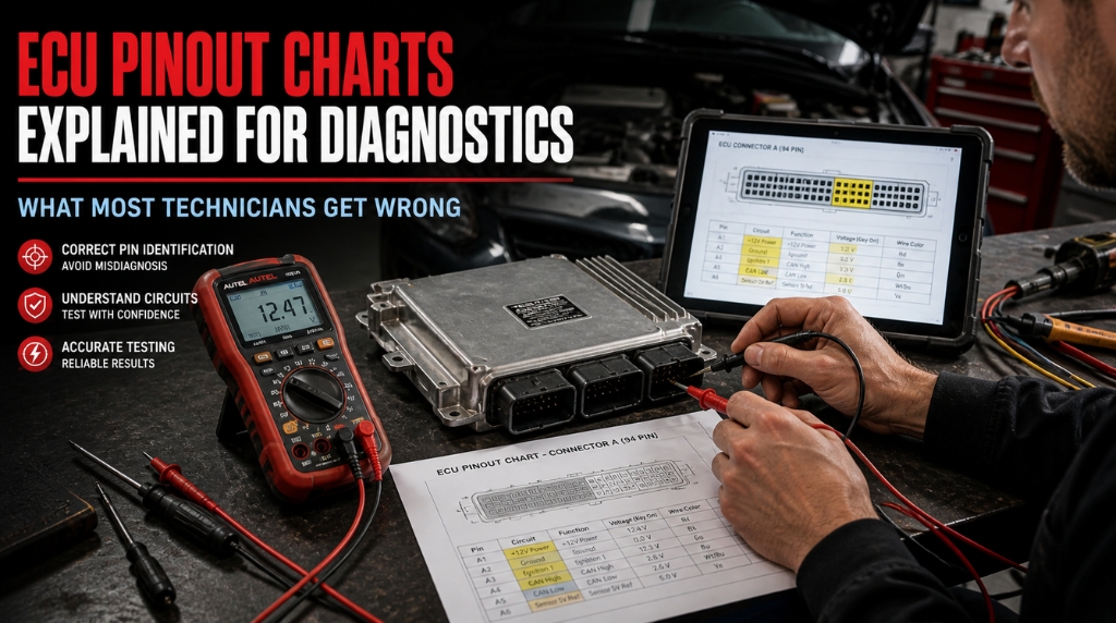
Correctly interpreting an ECU pinout chart is the most efficient way to resolve electrical faults. These charts map every terminal on an ECU connector, specifying their function, signal type, and voltage. For diagnostics, they allow technicians to accurately test power, ground, and sensor circuits directly at the computer.
This guide covers how to read, interpret, and apply ECUpinoutcharts in real diagnostic work, from connector identification to live circuit testing.
ECU Pinout Charts Explained for Diagnostics: The Reference Tool That Changes Everything
Many wiring faults persist because technicians use incomplete or misinterpreted pinout data. A comprehensive ECU pinout chart maps every connector pin detailing its number, function, signal, voltage, and color to eliminate guesswork during diagnostics.
Accurate diagnosis depends on understanding chart columns, ensuring correct connector orientation, and validating pinout data against live scan tool readings.
What an ECU Pinout Chart Actually Contains
Before you can use a pinoutchart for diagnostics, you need to know what you are reading. Each row in the chart corresponds to a physical pin on the ECU connector.
A standard ECUpinoutchart will include the following columns:
- Pin number: The unique identifier for each terminal in the connector housing
- Circuit function: What the pin does power supply, sensor input, actuator output, or communication line
- Signal type: Analog, digital, PWM (Pulse Width Modulation), frequency, or CAN bus
- Voltage reference: Expected voltage under key-on, engine-running, or key-off conditions
- Wire color: The factory harness color code for that circuit
|
Column |
What It Means in Diagnostics |
|
Pin Number |
Used to identify the correct terminal for backprobing or testing |
|
Circuit Function |
Tells you which system the pin belongs to (fuel, ignition, emissions, etc.) |
|
Signal Type |
Determines which test method to use (DMM vs. oscilloscope vs. scan tool) |
|
Voltage Reference |
The expected value your meter should display if the circuit is healthy |
|
Wire Color |
Confirms you are testing the correct wire in the harness |
Misidentifying even one column leads directly to a wrong test result. This is exactly why reading the chart from a vehicle-specific factory service manual matters far more than using a generic online pinout.
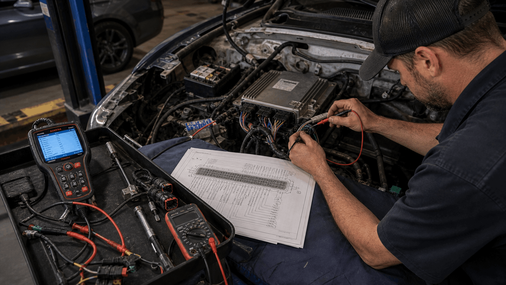
How to Orient the Connector Before You Test
This is the step that causes the most errors. The ECU connector can be viewed from two angles the ECU side (male pins pointing out) or the harness side (looking into the female sockets). Most pinoutcharts show the diagram as viewed from the ECU side.
If you flip that orientation, every pin number shifts position. Testing pin 12 on a flipped diagram means you are actually probing pin 23 on the real connector. That one mistake can generate false readings, mislead your diagnosis, and in some cases damage the circuit.
Follow these steps before every test:
- Identify the connector type — how many pins total, and how many rows
- Find the orientation note in your manual or pinout reference (usually labeled “as viewed from ECU” or “as viewed from harness”)
- Locate the physical reference marker on the connector — most have a locking tab, notch, or mold mark at a fixed corner
- Count pins from the reference marker to confirm your starting position
- Always verify the pin 1 location before measuring any circuit
For those working from digital workshop documents, understanding how to navigate interactive PDF workshop manuals efficiently can save significant time when cross-referencing connector orientation diagrams and wiring schematics: How to Navigate Interactive PDF Workshop Manuals.
Reading the Pin Function Groups in Any ECU
ECU connectors organize their pins into logical groups. Understanding these groups lets you navigate the chart faster and focus only on the circuits relevant to your fault code.
The five main pin function groups found in virtually every ECUpinout are:
Power and Ground Circuits. Essential for all ECU tests, these include constant battery supply (BATT/+B), switched ignition (IGN/term. 15), chassis ground (term. 31), and signal ground. Each requires individual testing; notably, a faulty signal ground can trigger numerous deceptive sensor faults.
Sensor Inputs: These pins receive data from the engine’s sensing network, MAF (Mass Air Flow), MAP (Manifold Absolute Pressure), TPS (Throttle Position Sensor), CTS (Coolant Temperature Sensor), and oxygen sensors. Most are 0–5V analog signals. The pinoutchart shows the expected voltage range at idle and under load.
Actuator Outputs: The ECU pins for commanding components such as injectors, coils, and fans typically use ground-side switching. To test these circuits, use an oscilloscope or noid light to verify the switching signal.
Communication Lines: Modern ECUs share data with other control modules via CAN (CAN-High and CAN-Low), K-Line, or LIN. These pins handle the communication between the engine ECU, transmission module, ABS module, and the diagnostic port. A fault on a CAN line can generate codes across multiple modules simultaneously.
Diagnostic and Immobilizer Circuits. Some ECU connectors include dedicated pins for immobilizer communication and workshop mode functions. These are often overlooked in general diagnostics but become critical in no-start and transponder fault scenarios.
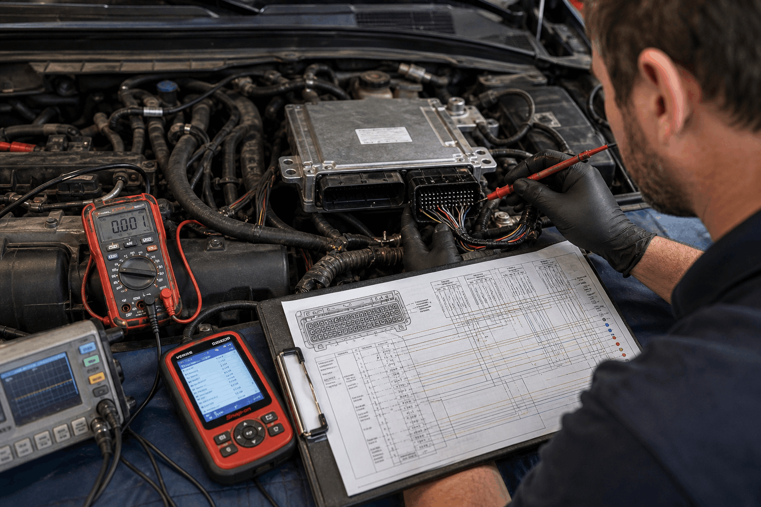
Using the Pinout Chart Alongside Live Scan Data
A pinoutchart alone is a reference. Paired with live diagnostics data from a scan tool, it becomes a precise testing framework.
Here is how the two work together in practice:
- Pull the active DTC and identify the affected circuit by code description
- Open the pinoutchart and locate the pin number assigned to that circuit
- Note the expected signal type and voltage from the chart
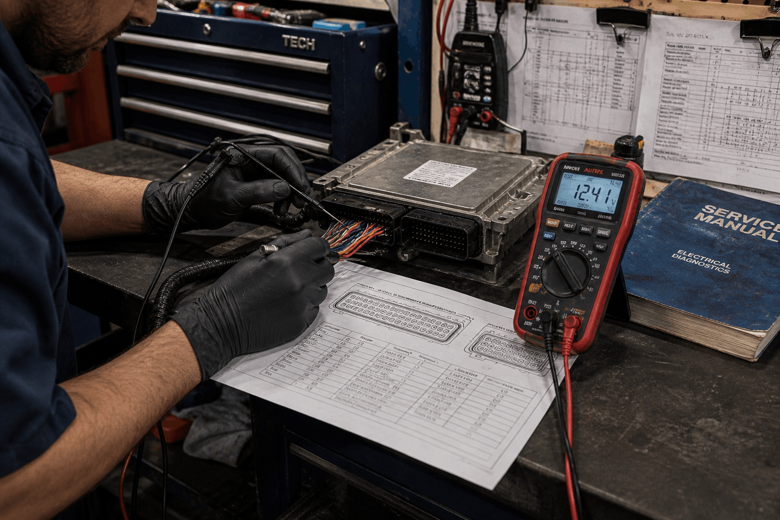
- Connect your DMM or oscilloscope to the correct pin using a backprobe or breakout box. Never pierce the wire insulation
- Compare your live reading against the chart reference value
- If the reading is out of range, use the full wiring diagram to trace the circuit upstream and downstream of the ECU
|
Test Type |
Tool to Use |
What the Pinout Chart Tells You |
|
Voltage present / absent |
Digital Multimeter |
Expected voltage (0V, 5V, 12V) at key-on |
|
Signal pattern |
Oscilloscope |
Signal type (PWM, frequency, analog ramp) |
|
Resistance check |
DMM in ohms mode |
Circuit continuity and expected resistance values |
|
Live data comparison |
Scan tool |
Sensor output at the ECU vs. chart spec |
This approach eliminates the habit of replacing parts solely based on code descriptions. The pinoutchart tells you what the circuit should do; your meter tells you what it is actually doing.
Common Pinout Mistakes That Derail a Diagnosis
Even with the correct chart open, certain habits consistently produce wrong results.
Incorrect year/variant choice. Layouts often change between model years. Even minor variations within an engine family, such as Bosch ME17 versions, can relocate ground pins or sensor inputs. Always verify the exact year, engine code, and ECU part number before testing.
Neglecting signal grounds. Technicians often focus only on power and chassis grounds. However, a degraded signal ground can affect sensor voltage references, leading to multiple faults in systems such as the fuel trim and throttle. Pinout charts list these as distinct pins; both must be tested.
Probing without proper tools. Inserting sharp probes into connectors can widen terminals, leading to intermittent connections. Use a breakout box or a dedicated backprobe tool to safely test live ECU circuits.
If you are sourcing your pinout reference material from online databases rather than a factory service manual, it is worth understanding the trade-offs in quality. This breakdown of Are Free Online Car Repair Manuals Safe covers what to look for and what to avoid, particularly when it comes to ECU wiring data, where accuracy is critical.
For the most reliable ECUpinout sources, factory service manuals remain the gold standard. This guide on Where to Download Genuine OEM Workshop Manuals is a solid starting point for locating verified, year-specific documentation for your vehicle.
The broader decision of when to use manual resources versus professional consultation is worth thinking through as well, especially for complex ECU electrical faults, where misdiagnosis can carry real costs: Digital Car Manuals vs. Mechanic Advice.
Conclusion
ECUpinoutcharts are the most underused tool in automotive diagnostics. They are not just reference sheets, they are structured diagnostic frameworks that, used correctly, tell you exactly what to test, where to test it, and what result to expect.
Get the orientation right. Match the chart to your exact ECU variant. Pair it with live-scan data and the appropriate test equipment. That combination is what turns an unclear electrical fault into a resolved, verified repair, without unnecessary parts replacement or guesswork.
Frequently Asked Questions
Accurate ECU pinout charts are essential for engine swaps where donor harnesses often conflict with the receiving vehicle. By cross-referencing signal types and voltages, you can correctly replicate all necessary inputs and outputs.
Without this data, swaps frequently suffer from poor performance, fault codes, or communication failures with other modules, such as the ABS or transmission. Factory service manuals provide the most reliable pinouts for these projects.
A pinoutchart focuses specifically on the ECU connector, listing each pin’s number, function, signal type, and voltage reference. A full wiring diagram traces every circuit from the ECU pin through the harness, connectors, fuses, and ground points all the way to the sensor or actuator at the end of the circuit.
In diagnostics, you typically start with the pinoutchart to identify which pin corresponds to a fault, then move to the full wiring diagram to trace the fault’s origin in the harness. Both documents are required for thorough electrical fault-finding. Neither one alone covers everything.
This usually happens because the chart is sourced from a different production run, regional market variant, or optional equipment level. Manufacturers often revise ECU connector assignments mid-production cycle without changing the model designation.
A vehicle sold in one region may have additional emission sensors or market-specific modules that occupy pins left unused in another region’s spec. Always confirm the ECU part number on the physical unit and match it exactly to the pinout document.
If two reputable sources conflict on the same point, the factory service manual for your specific VIN range is the correct authority.
The safest method uses a proper backprobe tool, a thin, blunt-tip probe specifically designed to slide alongside the terminal without widening the contact. Alternatively, a breakout box adapter plugs between the harness and the ECU, providing labeled test points for every pin without requiring contact with the connector itself.
Never use a sharp standard probe tip directly in the ECU terminal. The terminal contact force is factory-set, and even slight widening from an oversized probe can cause an intermittent connection that is nearly impossible to find afterward. This kind of self-induced damage is one of the most common sources of new faults created during diagnostics.
Standalone aftermarket ECUs from brands like Haltech, Link, MoTeC, and AEM generally use unique connector configurations and pin assignments.
While signal types are comparable, physical layouts differ, and some units feature software-configurable pins. To ensure accuracy when working with these systems, always consult the specific pinout chart for your exact model and firmware version.