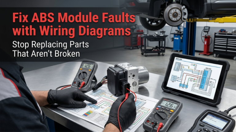
Repairing ABS module faults without wiring diagrams often leads to expensive, unnecessary replacements. When scanner C-codes appear, the circuit, not necessarily the module, is signaling a specific issue technicians frequently overlook.
Use pin-out diagrams and a DMM to verify power, ground, and harness integrity before condemning the module. By identifying connector-level issues such as corrosion or broken wires, you can perform targeted repairs, preventing the waste of money on new modules.
This guide walks through every step of that process: from reading the right codes, to tracing circuits on a wiring diagram, to verifying the repair through a live drive cycle.
Fix ABS Module Faults with Wiring Diagrams: What the Code Is Not Telling You
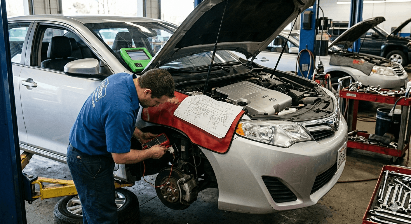
Most C-codes that reference ABS module failures are downstream symptoms, not confirmed component deaths. The code points to a circuit, not necessarily the module driving it. Using a vehicle-specific wiring diagram turns vague fault data into a testable circuit path, and that distinction alone separates a $40 repair from a $400 one.
Proper ABS fault diagnosis follows a fixed sequence: code retrieval, circuit mapping via diagrams, harness testing, power and ground verification, and then, only if all those pass, module condemnation. Skip any step, and you’re guessing.
Step 1: Scan for ABS Codes — The Right Way
Standard OBD-II scanners do not read ABS module codes. That’s the first trap. A basic code reader only accesses P-codes from the powertrain control module, not the C-codes stored in the Hydro-Electronic Control Unit (HECU).
You need a scan tool that communicates over the vehicle’s CAN bus and can access chassis modules directly. Connect it, then pull every stored and pending code, not just the first one.
ABS DTC Code Categories and What They Signal:
|
Code Type |
What It Indicates |
First Test |
|
C0035, C0040 (WSS circuit) |
Wheel speed sensor signal fault |
Check wiring continuity, not the sensor first |
|
C0550 (ECU performance) |
Internal module fault or power supply |
Verify B+ and ground at the module connector |
|
C0110 (pump motor circuit) |
Pump circuit open or shorted |
Test pump resistance (.5–5 Ohms spec) |
|
U0100 (lost CAN communication) |
Module not responding on the network |
Check CAN-High and CAN-Low for 60-Ohm spec |
|
C1165 (speed sensor circuit) |
Signal wire open or shorted |
Trace the wiring path using the harness diagram |
A “No Communication” result when connecting to the ABS module is particularly telling — the module is either not receiving power, has a failed ground, or the internal processor has failed entirely. You won’t know which until you open the wiring diagram and test the specific pins.
To systematically read these codes, the Read OBD-II Codes Using Manual Flowcharts guide outlines the decision-tree logic that prevents misidentification of root causes.
Step 2: Get the Right Wiring Diagram — Before Touching Anything

This step is non-negotiable. Generic diagrams pulled from forums or third-party databases frequently contain incorrect pin assignments for your specific build date and trim level. A wrong PIN number during testing either produces a false pass or damages a circuit.
Pull the wiring diagram from the factory service manual matched to your VIN. The ABS module connector pin-out will show:
- Battery positive (B+) supply pins — typically 12V with ignition ON
- Chassis ground pins — should measure under 0.5 Ohms to the battery negative
- Wheel speed sensor signal pins — each assigned to one of four corners
- CAN-High and CAN-Low communication lines — the network backbone
- Pump motor circuit pins — confirmed with resistance test at pump harness
The Find Your Factory Service Manual PDF by VIN resource walks through exactly how to locate and pull the correct documentation, including the pin-out pages for your exact vehicle configuration.
Step 3: Test the Harness Before Blaming the Module
The wiring harness running from the ABS module to each wheel speed sensor is the most common physical failure point, not the sensor, not the module. These wires move every time the wheel moves. After 10 to 20 years of constant flexing, internal wire breaks are routine even when the outer sheath looks perfect.
Visual inspection tells you almost nothing here. A wire can be broken internally with no visible damage. The only reliable method is electrical testing using a DMM with the connector unplugged from the module.
Harness Test Sequence Per ABS Sensor Circuit:
- Set DMM to resistance (Ohms) mode
- Backprobe the specific sensor pins at the ABS module connector using your wiring diagram
- Passive (variable reluctance) sensors: expect 800 to 1,400 Ohms across the two signal wires
- Active (Hall effect) sensors: backprobe with ignition ON and look for 5–12V reference voltage on the supply wire
- Wiggle the harness physically during resistance measurement — a sudden open circuit confirms an internal wire break
- Measure from each sensor pin to chassis ground to check for a short to ground condition (any reading below 10k Ohms is suspect)
If a harness circuit tests open and the sensor itself tests within spec at the wheel connector, the fault is definitely in the wiring between the two points, not the sensor or the module.
The ABS Warning Light Troubleshooting by Brake System Architecture resource maps, which show which harness sections are most vulnerable by vehicle architecture, are useful for narrowing the search area before running full continuity checks.
Step 4: Verify Module Power and Ground Circuits
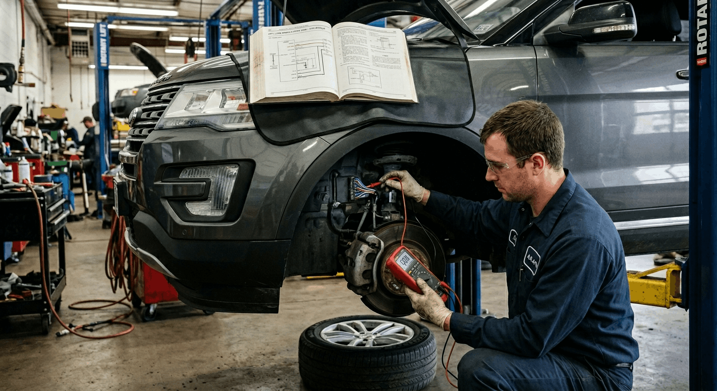
When harness checks pass clean, but the ABS module still fails to communicate or sets internal C-codes, the next test moves to the module’s own power and ground supply. A module receiving 11.2V instead of 12.6V because of a corroded B+ terminal will generate the same fault codes as a dead module.
With the wiring diagram identifying the correct pins:
Power Circuit Verification:
- Set DMM to DC volts
- Back-probe the B+ supply pins at the module harness connector with ignition ON
- Acceptable range: 11.5V minimum, ideally 12.4–12.8V
- Low voltage indicates resistance in the supply wire. Run a voltage drop test next
Ground Circuit Verification:
- Switch DMM to resistance mode, ignition OFF
- Measure from the ground pins on the connector to a known clean chassis ground point
- Acceptable reading: under 0.5 Ohms
- Any reading above 0.5 Ohms indicates corrosion in the ground path
Voltage Drop Testing Under Load:
- Reconnect the module connector, ignition ON
- Probe across the B+ supply wire (positive to positive terminal, negative to the module-side of the wire)
- A voltage drop exceeding 0.2V confirms excessive resistance the circuit needs repair, not module replacement
This kind of ground fault can cause the same current-starvation problems described in the Fix Parasitic Drains with Factory Schematics context: shared chassis ground-point corrosion affects multiple modules simultaneously.
Step 5: Test CAN Bus Communication Lines
When the scan tool shows a U-code alongside the ABS C-codes, the CAN bus network is involved. The ABS module communicates with the BCM, PCM, and stability control units over CAN-High and CAN-Low twisted-pair wires. A break or a short in these lines disrupts all communication.
CAN Bus Test Procedure (using wiring diagram to identify pins):
- With both network termination resistors intact and ignition OFF, measure resistance across CAN-High and CAN-Low at the ABS module connector
- Expected reading: approximately 60 Ohms (two 120-Ohm terminating resistors in parallel)
- A reading of 120 Ohms means one terminator is disconnected or open
- A reading of 0 Ohms (near zero) indicates a short between CAN-High and CAN-Low
- Open circuit (OL) reading indicates a break in the network wiring
For deeper connector-level testing at the module interface, the ECU Pinout Charts Explained for Diagnostics guide provides pin mapping methodology that applies directly to ABS module connectors on multi-bus architectures.
Step 6: Condemn the Module Only After All Tests Pass
If power supply tests pass, ground resistance is below 0.5 Ohms, all four sensor harness circuits test within spec, and the CAN bus shows 60 Ohms, yet the ABS module still sets internal solenoid or memory fault codes. Only then is module replacement justified.
Internal failures that genuinely require module replacement or rebuilding include:
- Solenoid circuit faults where individual valve driver transistors have failed inside the HECU
- Memory error codes that persist through multiple ignition cycles after all external circuits are confirmed good
- Pump motor internal codes after verifying the pump motor harness tests at 0.5–5 Ohms
Replacing the module without completing Steps 1 through 5 risks installing a new module into the same wiring fault that destroyed the original one. The sequence is the repair.
Conclusion
ABS module faults are almost never about the module. The wiring harness, power supply, ground integrity, and CAN bus continuity collectively produce more confirmed ABS failures than internal module hardware ever does.
The wiring diagram is the diagnostic instrument the DMM is just the tool that reads it. Work the circuit from the outside in, verify every connection specified by the pin-out, and the actual fault will reveal itself before any parts are ordered.
That process is what separates a fast, accurate repair from an expensive parts-swapping cycle.
Frequently Asked Questions
Yes, and it happens far more often than most people expect. Corrosion on the module connector pins creates resistance in the circuit, which the ECU interprets as a signal anomaly or dropout from the connected sensor.
The wiring diagram maps each pin to its circuit, so a targeted resistance measurement at a corroded pin will show a higher resistance than the spec calls for, near-zero.
Cleaning the terminals with electrical contact cleaner and a fine brass brush, followed by dielectric grease application, resolves a significant percentage of ABS C-codes that appear to indicate sensor or module failure.
Always inspect the connector before assuming the component is bad.
Passive, or variable reluctance, wheel speed sensor circuits measured at the ABS module connector should typically read between 800 and 1,400 Ohms across the two signal wires. This measures the combined resistance of the sensor coil and the full wire run from the sensor to the module.
A reading of OL (open circuit) confirms a broken wire or disconnected sensor. A reading near zero Ohms indicates a short circuit in the wiring or internally inside the sensor.
Always cross-reference the specific specification from the vehicle’s factory service manual, as some applications have tighter acceptable ranges depending on sensor design.
A returning ABS fault code after clearing almost always indicates that the underlying circuit condition remains present and the ECU re-detects it on the next drive cycle. If the sensor tests pass at rest but the code returns during driving, the wiring has an intermittent internal break that opens only when the harness flexes during suspension movement.
The correct test is to wiggle and flex the harness actively during resistance testing to replicate the failure. You can also monitor live wheel-speed-sensor PIDs on your scan tool during a slow test drive, a sensor dropping to 0 mph while the vehicle moves confirms the intermittent brake location.
Yes, and this is a frequently missed root cause. The ABS module is highly sensitive to fluctuations in the supply voltage. An alternator producing irregular voltage, either above 15V or dropping below 11.5V under load, causes the module to log supply voltage faults and sometimes wheel speed sensor codes simultaneously.
A simple charging system voltage test under electrical load reveals this pattern. If the wiring diagrams and harness all test correctly, but multiple unrelated C-codes persist, always check the charging system output before ordering any ABS components. This diagnostic step costs nothing and prevents an expensive misdiagnosis.
The distinction depends on which internal circuit has failed. Module rebuilds address common hardware failures on the electronic board, such as failed transistors controlling solenoid valve drivers and pump motor circuits, which are frequently repairable without replacing the entire Hydro-Electronic Control Unit.
A rebuild is appropriate when the physical module housing is intact, when the HECU connector and valve block are undamaged, and when the specific fault codes point to a known repairable internal component.
Full replacement is necessary when the processor has failed completely, when the valve block or motor has internal mechanical damage, or when the module has been exposed to water intrusion that has corroded the circuit board beyond service.