
Read auto wiring diagrams to trace shorts before blindly replacing parts, or you could waste hours chasing the wrong circuit while the real fault keeps blowing fuses and damaging wiring. One hidden short can drain the battery overnight, melt insulation inside the harness, or leave critical systems dead without warning.
The fastest way to find a short is to start with the factory wiring diagram, isolate the affected fuse and circuit path, then trace power flow step by step using a multimeter and ground checks. That approach cuts down guesswork and helps pinpoint faults far faster than random testing.
This guide explains how to read auto wiring diagrams correctly, understand circuit symbols and ground paths, identify short-to-ground problems, and trace electrical faults using a practical diagnostic process trusted by experienced technicians.
Read Auto Wiring Diagrams to Trace Shorts: What Factory Diagrams Reveal First
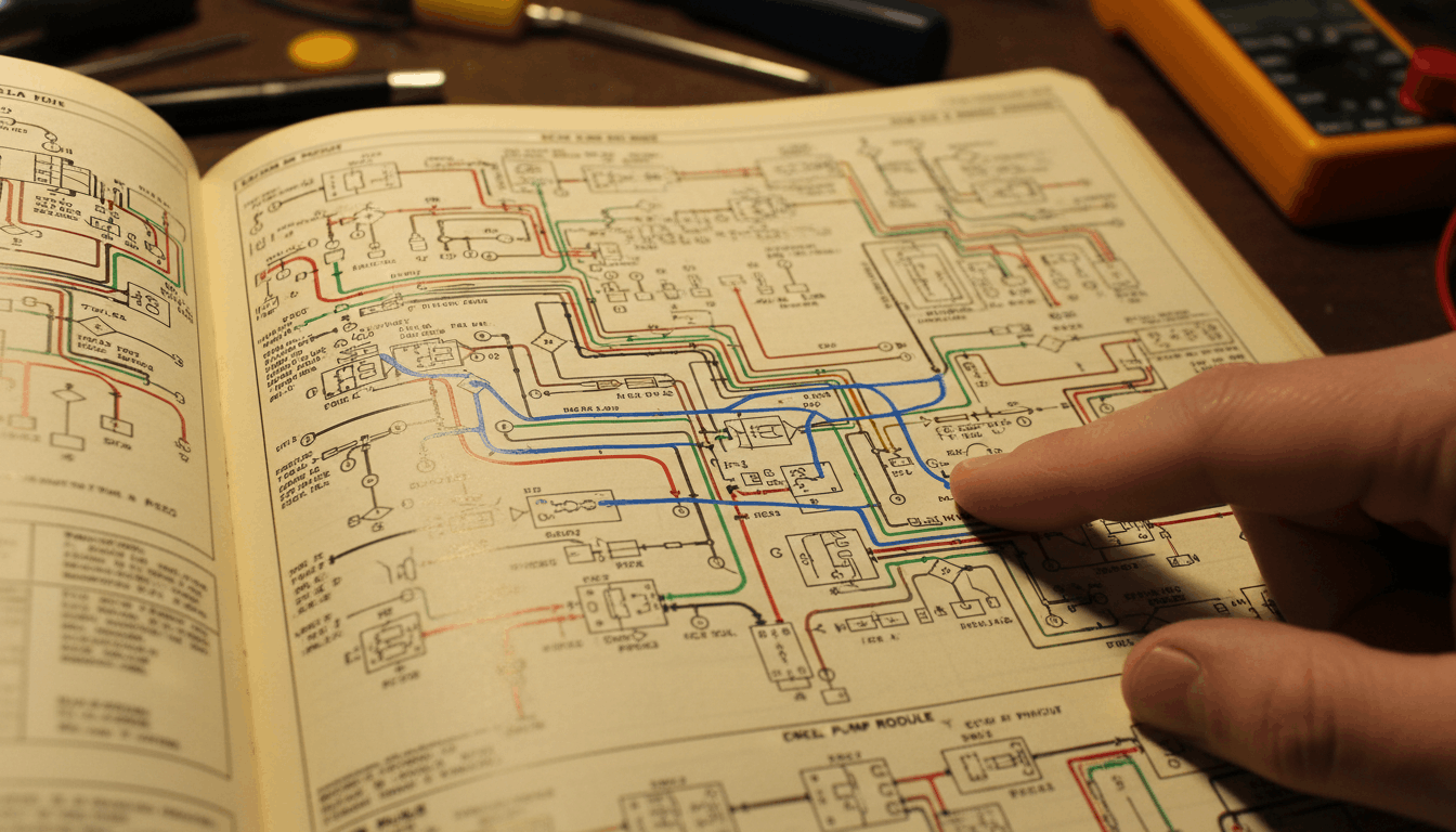
Most technicians grab a test light and start poking wires before they ever open a diagram. That approach works sometimes, but it doubles diagnostic time on complex faults. A wiring diagram shows the complete current path, every ground location, every splice point, and every connector cavity before you touch a single terminal. Mastering this map is what separates a two-hour repair from a two-day headache.
What Every Wiring Symbol Actually Tells You

Understanding the symbols on a wiring diagram is the required first step before any short tracing can begin. Skipping this causes technicians to misread circuit paths and test the wrong wires entirely.
Every symbol on an auto wiring diagram has a direct real-world meaning:
- Straight horizontal or vertical lines represent physical wires and conductors
- Zigzag lines represent resistors or electrical loads drawing current
- Circles with an X represent light bulb components in the circuit
- Downward-pointing triangles represent chassis ground connection points
- Dashed lines represent shielded wires that run near interference sources
- Boxes with numbered terminals represent connectors and multi-pin plugs
|
Symbol |
Real-World Component |
Why It Matters for Short Tracing |
|
Straight line |
Wire or conductor |
Defines the current path to follow |
|
Zigzag |
Resistor or load |
Normal resistance confirms no short |
|
Downward triangle |
Ground point |
Common short destination |
|
Dashed line |
Shielded wire |
Chafe points near grounded metal |
|
Box with terminals |
Connector plug |
Split points for isolation testing |
|
Circle with X |
Bulb or lamp |
The load that disappears when the short exists |
Splice points on the diagram indicate where multiple wires share a single connection node. A short at a splice affects every branch of that splice simultaneously, which explains why multiple fuses blow at once on some faults.
How to Spot a Short Circuit on Any Diagram

A short circuit on a wiring diagram hides in the path between the power source and the load. Reading the diagram correctly reveals exactly where to look before testing anything.
Start by locating the blown fuse in the diagram’s fuse box legend. Every fuse on the diagram has a circuit number and a list of components it protects. That information immediately shows you the full scope of the fault zone.
Key short circuit patterns visible directly on a wiring diagram:
- Circuits with long wire runs through door jambs, firewalls, or under carpet are chafe-risk zones
- Multiple loads sharing one fuse without individual protection means one short kills all of them
- Shared ground paths near each other in the chassis can cross-contaminate two circuits
- Door and trunk harness routing through rubber grommets is the most common physical short location
At this stage, cross-referencing parasitic drains using factory schematics adds critical context. A slow parasitic drain and an intermittent short look identical on a multimeter until you isolate the circuit using the diagram’s load list.
Step-by-Step: Trace a Short in 5 Precise Moves
Now that the circuit is mapped on the diagram, the isolation process follows a binary search pattern. This method dramatically reduces diagnostic time compared to random probing.
Step 1: Pull the fuse and disconnect all circuit loads
Remove the blown fuse from the fuse box. Using the wiring diagram, identify every component that the fuse feeds and disconnect each one at its connector. This removes the devices, leaving only the wiring in the test circuit.
Step 2: Set your multimeter to resistance mode
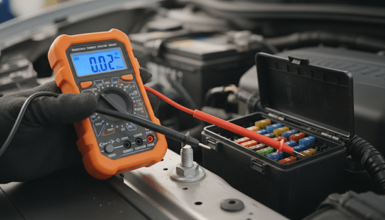
Place one probe on the wire at the fuse box terminal. Place the other probe on a clean chassis ground point. A reading near zero Ohms confirms a short to ground exists somewhere in that wire path. A reading of infinite resistance indicates the short is within one of the disconnected loads, not in the wiring.
For exact resistance specifications by component, multimeter sensor testing via workshop manuals provides the baseline values needed to compare your readings against known-good specs.
Step 3: Find the midpoint connector on the diagram and split the circuit
Locate the connector closest to the midpoint of the circuit path on your wiring diagram. Disconnect it, then retest the resistance to ground at the fuse box end. If the short disappears, the fault is in the section past the connector. If it remains, the fault is between the fuse box and that connector.
Step 4: Keep splitting until the fault zone is small
Repeat Step 3 using the next connector shown in the fault-confirmed section of the diagram. Each split halves the remaining search area. Most wiring faults are isolated to a short section of wire within three or four splits.
Step 5: Physically inspect the isolated section
Once the fault is narrowed to a short wire segment, perform a close visual inspection:
- Chafed insulation against sharp metal edges on body panels or brackets
- Pinched wires caught in door hinges, firewall grommets, or seat track runners
- Melted insulation near heat sources, including the exhaust, catalytic converter, or engine block
- Corroded connectors where terminal contamination bridges two pins internally
|
Step |
Action Taken |
Tool Required |
|
1 |
Pull the fuse, disconnect all loads |
Fuse puller, wiring diagram |
|
2 |
Test resistance to chassis ground |
Multimeter set to Ohms |
|
3 |
Disconnect the midpoint connector, retest |
Wiring diagram for the connector location |
|
4 |
Repeat splits in the fault-confirmed section |
Multimeter, diagram |
|
5 |
Visual inspection of the isolated segment |
Flashlight, pick set |
Wire Color Codes and Circuit Numbers Decoded

Wire color codes on auto wiring diagrams are not standardized across manufacturers. A red wire on a Ford schematic carries a completely different meaning than a red wire on a Toyota or Honda diagram.
Always reference the color code legend printed on the first page of your specific wiring diagram set. Most manufacturers also use a base color with a stripe color to indicate sub-circuits on the same color family. Both colors matter for correct wire identification.
Circuit numbers are the most reliable tracking tool across multi-page diagrams. Each wire carries a printed circuit number that stays consistent across every page of the diagram where that wire appears. Following the circuit number prevents you from accidentally switching to a parallel circuit that looks similar but feeds a different system entirely.
When the short is near the engine control module (ECU), ECU pinout charts for diagnostics clarify which terminal cavity connects to which circuit before you probe any control module connector pin.
When Fault Codes Guide Your Diagram Search
Some shorts trigger a stored diagnostic code before the fuse even blows. These codes provide a direct entry point into the wiring diagram, eliminating the need to guess which circuit to check first.
Cross-reference the fault code with the affected system in your diagram index. The code narrows you to one subsystem. The diagram then shows the exact wire path, ground points, and connector locations within that subsystem.
Combining OBD-II codes with manual flowcharts alongside your wiring diagram creates a two-step diagnostic approach that is significantly faster than starting from the fuse box on a complex vehicle with multiple control modules sharing circuit paths.
Conclusion
Tracing a short circuit without a wiring diagram is slow, risky, and often creates new faults while searching for the original one. Reading the auto wiring diagram first gives you the circuit path, ground locations, splice points, and connector split locations before a single probe touches a terminal.
Follow the blown fuse to its circuit, disconnect the loads, split the wiring at the connectors shown on the diagram, and test resistance to ground at each split.
The fault zone shrinks with every split until a short wire segment remains for visual inspection. Color codes and circuit numbers keep you on the correct wire through every page of a complex diagram.
Frequently Asked Questions
Tracing a short without a wiring diagram is possible, but significantly slower and far more likely to cause additional damage. Without the diagram, there is no way to know which components share a fuse, where the ground points are located, or where the connectors sit in the harness for split testing.
Technicians end up probing random wires and often disturb connectors that were working fine. A wiring diagram reduces a multi-hour search to a 30-minute isolation process on most faults.
Even a basic OEM diagram accessed through a manufacturer subscription portal is worth the cost before touching a single wire.
Set the multimeter to resistance mode (Ohms) when testing for a short to ground. Remove the fuse first and disconnect all loads on that circuit before testing.
Place one probe on the circuit wire at the fuse box and the other on a clean chassis ground point. A reading near zero Ohms confirms that a direct path to ground exists in the wiring.
A very high or infinite reading means the short is inside one of the disconnected components, not the wire run itself. Always power the circuit off completely before switching to resistance mode to protect the multimeter from damage.
A fuse that blows immediately after replacement means the underlying short circuit has not been repaired. The fuse is a protective device that sacrifices itself to prevent the wiring harness from overheating and burning.
Replacing it without fixing the fault simply restores current flow into the damaged wire section. Locate the blown fuse on your wiring diagram, identify every circuit that the fuse protects, and test each wire and component for resistance to ground with the fuse removed.
Common causes include chafed wires at body panel edges, pinched harnesses at door hinges, and corroded connectors bridging two terminals internally.
Door harness shorts are among the most common wiring faults because the wires flex thousands of times through the hinge area as the door opens and closes. Open your wiring diagram to the door circuit section and identify all wires routed through the door-to-body transition point.
Disconnect the door harness connector at the body pillar and test each wire for resistance to ground. The rubber grommet where wires pass from the door to the body pillar is the most common failure point.
Cracked or collapsed grommets allow insulation to contact the metal edge of the body opening, creating a clean short to ground that only occurs when the door is in certain positions.
Factory wiring diagrams from the original manufacturer are always more accurate than aftermarket alternatives for short tracing work. OEM diagrams include exact wire colors, circuit numbers, connector cavity positions, splice locations, and component ground points specific to your vehicle’s exact build date, market, and trim level.
Aftermarket diagrams are generalized across wide model-year ranges and frequently omit trim-specific variants or mid-production wiring revisions. For short tracing where a single incorrect connector cavity position can send you to the wrong wire, OEM accuracy is not optional.
Aftermarket diagrams are acceptable for basic reference but should not be trusted for precision isolation testing.