Trying to read, interpret, and apply exploded-view manual diagrams without a clear method results in costly reassembly errors almost every time. Most people stare at these diagrams and freeze because no one taught them the correct starting point. One wrong part sequence can damage components worth hundreds of dollars.
To interpret diagrams effectively, start with the parts list, follow the numerical order from the exterior inward, and confirm all part numbers before assembly. These 3D isometric illustrations use a “controlled explosion” to show assembly paths.
Navigation requires identifying the main housing, linking callouts to the Bill of Materials (BOM), and following dashed lines to see how parts integrate.
This article covers every step of reading exploded-view diagrams, from understanding the layout logic to identifying part relationships and avoiding the most common misreading mistakes.
How to Read Exploded View Manual Diagrams: What Every Step Actually Means

Exploded view diagrams are technical illustrations that show the components of a system pulled apart along a common axis. Understanding how to read these manual diagrams correctly saves time, reduces errors, and gives you a clear mental map of how every part connects. This section covers the full process from first glance to final verification.
Start With the Parts List, Not the Image
Most technicians jump straight into the diagram without checking the parts list first. That single habit creates confusion almost immediately in any repair job.
Before studying any exploded view, locate the parts list or parts index that accompanies the diagram. This list assigns a number to every component shown in the illustration. Each number corresponds directly to a row in the list, which includes the part name, part number, and required quantity.
- Scan the full parts list before touching the image
- Note which parts appear more than once (the quantity column matters)
- Flag any parts marked as “assembly required” since they contain their own sub-diagrams
- Cross-reference part numbers against your genuine OEM workshop manuals to confirm accuracy
When you understand what every number represents before studying the image, the entire exploded view becomes logical rather than overwhelming.
Understand the Axis and Explosion Direction

Every exploded view diagram is built around a central axis. Parts are “exploded” outward from that axis in the exact order of assembly or disassembly.
The explosion direction directly tells you the assembly sequence. Parts shown furthest from the core are installed last or removed first. Parts closest to the center are the foundational components, and this spatial logic is consistent across nearly all manual diagrams.
- Identify the central component first, usually the housing or base unit
- Trace the axis line from the center outward
- Parts along the same axis line go together in sequence
- Parts branching off at angles are sub-assemblies or accessories
Recognizing the axis direction is what separates fast, accurate diagram reading from slow, error-prone guessing.
Follow the Numbered Sequence Step by Step
Numbers on an exploded view are not random. They follow a strict logical order that reflects either the assembly or disassembly sequence, depending on the manual’s intent.
Most workshop manuals number parts from the outside in, meaning part 1 is the first thing removed and the last thing installed. Some manuals reverse this convention. Always check the manual’s legend to confirm which approach is used.
|
Numbering Convention |
Starting Point |
Typical Use |
|
Outside-In |
External cover or fastener |
Disassembly guides |
|
Inside-Out |
Core component or housing |
Assembly guides |
|
Mixed |
Depends on sub-assembly |
Complex engine diagrams |
- Read all callout lines carefully since they point from the number to the exact part
- Never assume a number’s position equals its installation order without checking the legend
- When numbers skip (e.g., 1, 2, 5, 6), look for a sub-diagram on another page
If you access these diagrams through interactive PDF workshop manuals, you can often click part numbers to jump directly to the specifications, which significantly speeds up this step.
Read Callout Lines and Symbols Correctly
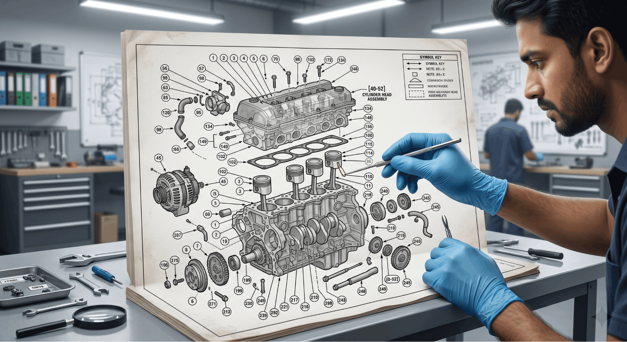
Callout lines are the thin lines connecting a number to its corresponding part in the diagram. Misreading these lines is one of the top causes of reassembly errors in any shop.
A callout line always points to a specific part, not a general area. If the line ends with an arrowhead, it points to the exact surface or edge of that component. If it ends with a dot, it references the entire part or sub-assembly.
- Arrow tip: Points to a specific face, edge, or hole
- Dot tip: References the entire component
- Bracket: Groups multiple parts that install as a single unit
- Dashed line: Indicates a hidden or internal component
Symbols within the diagram also carry meaning. A circle around a number typically signals a fastener torque specification. A triangle or flag symbol often marks a critical assembly step. These are all defined in the manual’s legend page, which you should read before interpreting any diagram.
Verify Against a Second Source Before Assembly
No exploded-view diagram should be used in isolation, especially for critical systems such as brakes, steering, or fuel delivery on any vehicle.
After mapping every part using the diagram, verify your part list against at least one additional source. A factory service manual PDF, VIN-specific to your exact vehicle build, is the most reliable option. VIN-specific documentation catches variant differences that generic diagrams often miss entirely.
- Compare part numbers to VIN-specific documentation
- Check for model-year revisions that may have updated part numbers
- Confirm torque specs from the manual’s specification table, not the diagram alone
- If unsure between two manual formats, reviewing PDF manuals vs interactive repair software helps you decide which format provides the most reliable detail
This verification step takes five minutes and prevents hours of rework.
Common Mistakes When Reading Exploded View Diagrams

Even experienced technicians make predictable errors when reading exploded view manual diagrams under time pressure and deadline stress.
The most common mistake is treating the diagram as a photograph rather than a schematic. A diagram shows relationships and sequences, not realistic proportions. Parts that appear small in the image may be large in real life.
- Skipping the legend: Symbols and conventions differ between manufacturers
- Ignoring quantity columns: Installing one bolt where three are required causes failures
- Misidentifying mirrored parts: Left and right components often look identical in a diagram
- Using outdated diagrams: Always confirm you have the correct manual revision for your specific model
To avoid this entirely from the start, choosing the right workshop repair manual ensures your diagrams match your exact component specifications every time.
Conclusion
Reading exploded view manual diagrams is a learnable skill that follows clear, consistent logic once you understand the rules. Start with the parts list, recognize the axis direction, follow the numbered sequence, and always verify against a VIN-specific or OEM source before assembly.
These steps remove the guesswork entirely and make even complex diagrams manageable. The next time you open a manual, you will know exactly where to look and what each element actually means.
Frequently Asked Questions
An exploded view diagram pulls all components apart along an axis to show how they fit together in sequence. A cutaway diagram slices through a component to reveal its internal structure without separating the parts. For repair and reassembly work, exploded views are more practical because they clearly show part placement and the installation order.
Cutaway diagrams are more useful for understanding how something functions internally rather than how it is built or serviced.
Unnumbered parts in an exploded view are typically standard hardware items, such as generic bolts, washers, or gaskets, that are not sold individually. These parts must be purchased as part of a kit or sub-assembly.
Some manuals exclude common fasteners from numbering to keep the diagram readable and uncluttered. If you encounter un-numbered parts, check the sub-assembly description or hardware kit listing in the accompanying parts catalog to identify them correctly before ordering.
Check the manual’s revision date, edition number, or document control header, which is usually printed on the cover page or the footer of each section. For vehicle-specific diagrams, always cross-reference the manual edition against your VIN to confirm it covers your exact production year and build variant.
Manufacturers update diagrams when parts are superseded or assembly processes change, so using an outdated diagram on a revised component is one of the most common causes of assembly errors found in professional repair shops.
Using a diagram from a different model year carries real risk, especially for systems that changed mid-production. Manufacturers frequently revise component layouts, fastener specifications, and part numbers from year to year.
A diagram from even one year prior may show a different sealing arrangement or bracket design than what is actually on your unit. Always use a diagram sourced from the exact year, trim level, and build specification of your component to avoid installing incorrect parts or missing critical assembly steps.
Digital diagrams from current OEM databases are generally more accurate than printed manuals because they are updated in real time when part numbers change or assembly steps are revised. Printed manuals reflect the information available at the time of printing and may be several revisions behind.
That said, the accuracy of a digital diagram depends entirely on the source. Always confirm that the digital manual you are using is from an authorized or OEM-approved platform rather than a third-party site that may host outdated or incomplete diagrams.