Posted on

Brake Warning Light: Hydraulic vs Electronic Fault Isolation: How to Identify the Real Cause Before It’s Too Late

A focused mechanic inspects a glowing red brake warning light on a car's dashboard inside a professional garage.

When the brake warning light and the hydraulic electronic fault isolation alert appear, they signal more than routine maintenance. A brake fault can indicate fluid loss, sensor failure, or an electronic malfunction, each of which can reduce stopping power and put lives at risk. Ignoring this warning increases the chance of sudden brake failure.

OEM service manuals provide the most reliable procedures for isolating brake warning light faults. By following structured steps, drivers and technicians can separate hydraulic issues from electronic faults, ensuring accurate diagnosis and preventing costly mistakes.

This article will explain the most common causes of brake warning lights, outline hydraulic vs. electronic fault-isolation methods, highlight repair costs, and emphasize the safety risks of neglecting proper diagnostics. Readers will gain practical insights to keep vehicles safe and compliant.

Brake Warning Light: Hydraulic vs Electronic Fault Isolation: Why Accurate Diagnosis Prevents Costly Mistakes

A focused automotive technician in a modern garage compares a digital diagnostic manual on a tablet to a glowing red brake warning light on a vehicle dashboard.

The brake warning light is one of the most critical alerts on any dashboard. It can indicate issues in the hydraulic system, such as fluid leaks or pressure loss, or in the electronic system, like sensor faults or module errors. 

Using OEM manuals for structured fault isolation ensures technicians and drivers can distinguish between hydraulic and electronic causes, preventing misdiagnosis and ensuring safe braking performance.

Common Brake Warning Light Causes Explained

Drivers often assume that the brake warning light only indicates low fluid levels, but multiple factors can trigger it.

  • Hydraulic faults: Leaks, worn seals, or low fluid levels.
  • Electronic faults: Sensor misreads, wiring damage, or module errors.
  • Mixed issues: Hydraulic wear leading to electronic miscommunication.

Older vehicles are more likely to experience hydraulic problems. For example, the 1994 Buick LeSabre 3.8L Workshop Service Repair Manual emphasizes fluid checks as the first diagnostic step when the warning light appears.

Hydraulic Fault Isolation in Brake Systems

A mechanic measures hydraulic pressure on the master cylinder of a 1982 Buick Skylark in a gritty vintage workshop.

Hydraulic fault isolation focuses on fluid pressure and mechanical components. OEM manuals provide structured steps to confirm hydraulic integrity.

  • Inspect fluid reservoir levels.
  • Check for leaks in brake lines and calipers.
  • Measure hydraulic pressure against OEM specifications.
  • Test master cylinder performance.

Classic models like the 1982 Buick Skylark 2.8L VIN Z Workshop Service Repair Manual detail these procedures, showing how hydraulic isolation dominated before electronic systems became standard.

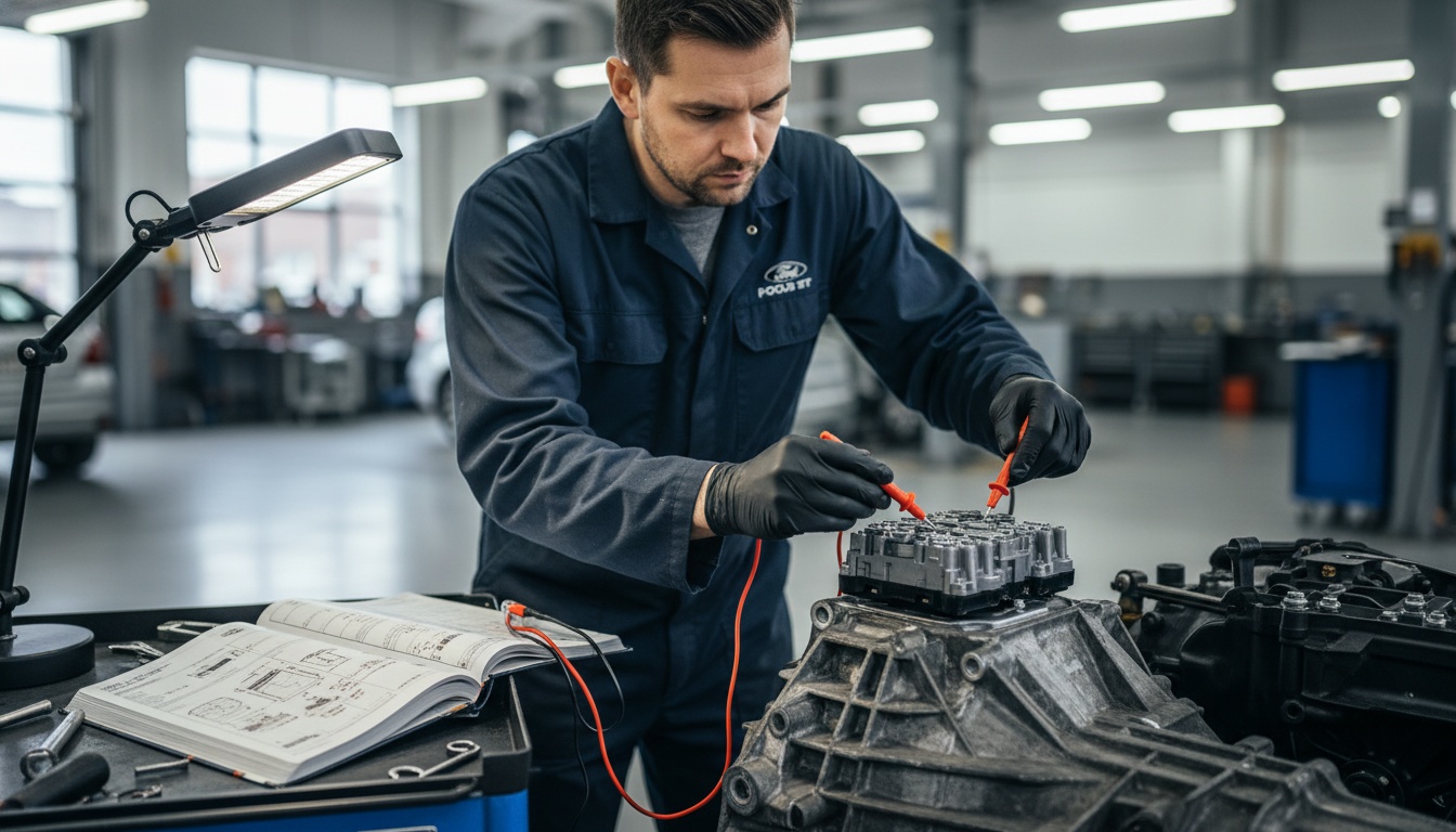
Electronic Fault Isolation and Sensor Diagnostics

Electronic fault isolation requires structured sensor testing and module checks.

  • Scan brake system codes with OEM-approved tools.
  • Test wheel speed sensors for accurate signals.
  • Inspect wiring harnesses for continuity.
  • Validate module outputs against OEM thresholds.

Modern SUVs like the 2018–2021 Buick Enclave Workshop Service Repair Manual highlight how electronic diagnostics are essential, as advanced brake systems rely heavily on sensor communication.

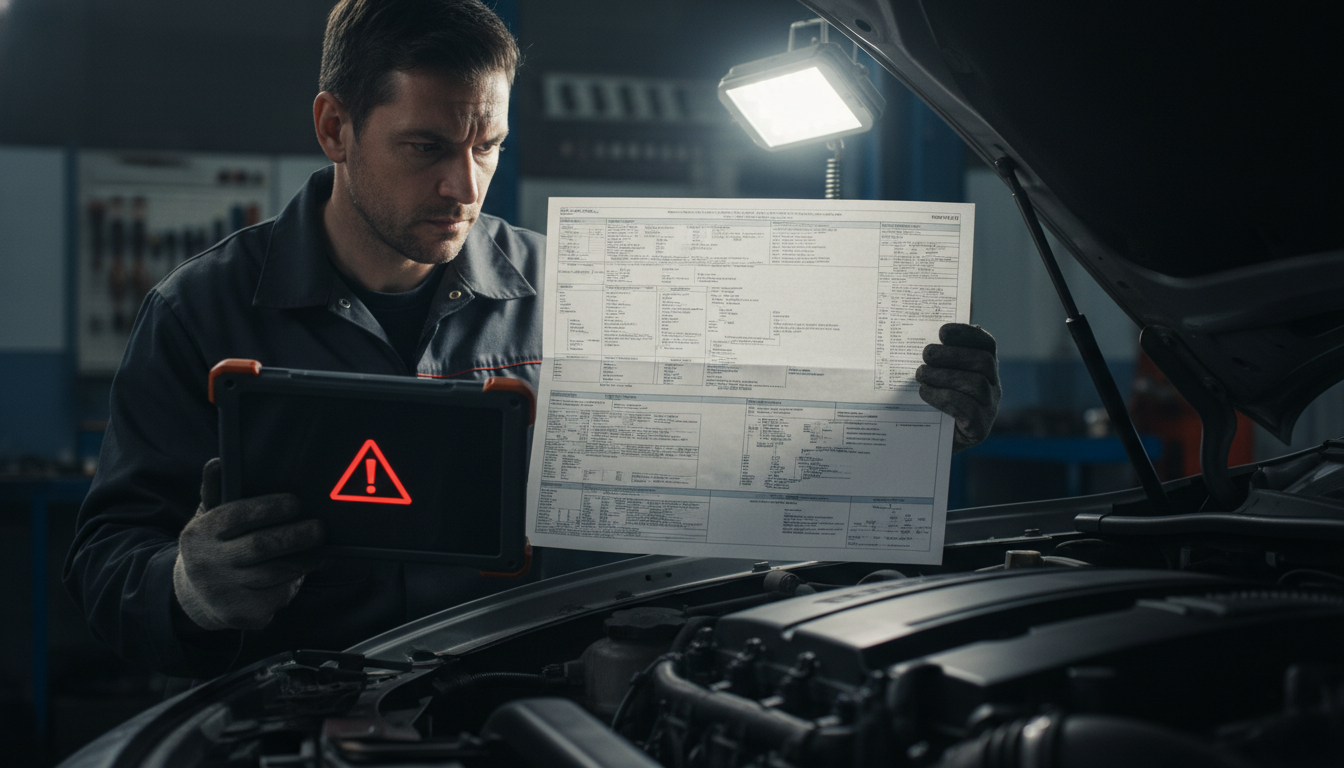
DIY Brake Warning Light Checks You Can Try Safely

A car owner sits in a sedan in a bright garage while holding an illuminated OBD-II scanner with a workshop manual on the passenger seat.

Some fault isolation steps can be attempted at home with minimal tools.

  • Check brake fluid levels regularly.
  • Inspect visible brake lines for leaks.
  • Use a basic OBD-II scanner to read brake codes.
  • Compare readings against OEM manual specifications.

Mid-size sedans like the 2013 Buick Verano 2.4L Workshop Service Repair Manual provide clear guidance for drivers attempting basic checks before visiting a mechanic.

Repair Costs Linked to Hydraulic vs Electronic Faults

Understanding repair costs helps drivers plan.

Fault Type Typical Cost Range Notes
Hydraulic fluid replacement $80–$150 Prevents pressure loss
Brake line repair $200–$500 Labor-intensive
Sensor replacement $100–$250 Common in modern vehicles
Module repair $400–$1200 Requires OEM programming

AWD platforms like the 2012 Buick Enclave AWD 3.6L Workshop Service Repair Manual emphasize how hydraulic and electronic systems interact, often increasing repair complexity and cost.

Safety Risks of Ignoring the Brake Warning Light

Ignoring the brake warning light can lead to serious safety risks.

  • Reduced braking power: Hydraulic leaks lower pressure.
  • Erratic braking: Faulty sensors confuse the system.
  • Longer stopping distances: Both hydraulic and electronic faults compromise control.
  • Higher accident risk: Unchecked faults increase the probability of failure.

OEM manuals stress immediate action. The 2018–2021 Buick Enclave Workshop Service Repair Manual notes that delayed fault isolation increases the risk of complete brake failure.

Conclusion

The Brake Warning Light: Hydraulic vs Electronic Fault Isolation approach ensures drivers don’t rely on guesswork or risk safety by ignoring critical alerts. Fluid checks, sensor diagnostics, and module inspections each demand unique steps. By following OEM manuals across Buick models—from the 1982 Skylark to the 2018–2021 Enclave—drivers and technicians can protect vehicles, reduce costs, and maintain safety.

Practical takeaway: Always align brake warning light diagnostics with OEM manuals. Structured fault isolation reveals the real issue, ensuring accurate repairs and safer driving.

Frequently Asked Questions

Yes, many modern systems detect pad wear electronically, which can activate the warning light.

It should be done immediately when the light comes on, and rechecked during routine brake service intervals.

They can. Regenerative braking systems add electronic complexity, making fault isolation more dependent on sensor testing.

Absolutely. Sensor misreads often confuse the control module, which is why OEM-guided isolation is essential.

No, even short trips can worsen hydraulic or electronic faults, increasing the risk of sudden brake failure.

Posted on

TPMS Light Reset and Sensor Testing Using Service Manuals: Critical Steps Drivers Overlook That Could Compromise Safety

A technician in a professional garage tests a car tire sensor using a diagnostic tool near a service manual and glowing TPMS warning light.

When the TPMS Light Reset Sensor Testing alert appears, it signals more than just low tire pressure. A malfunctioning sensor or failed reset procedure can leave the system unreliable, increasing the risk of blowouts, uneven wear, and dangerous driving conditions. Ignoring this warning compromises both safety and vehicle performance.

OEM service manuals provide the most accurate TPMS reset and sensor testing procedures. These manuals guide technicians and drivers through structured steps, ensuring the system is recalibrated correctly and sensors are tested against factory specifications.

This article will explain the most common causes of TPMS light, outline reset procedures using service manuals, detail sensor testing methods, compare direct vs. indirect systems, and highlight the risks of neglecting proper diagnostics. Readers will gain practical insights to keep their vehicles safe and compliant.

TPMS Light Reset and Sensor Testing Using Service Manuals: Why Proper Calibration Matters More Than You Think

A professional mechanic uses a handheld diagnostic tool and service manual to reset a glowing TPMS warning light on a vehicle's dashboard inside a modern auto shop.

The TPMS light is not just a minor dashboard symbol. It’s a direct warning that your tire pressure monitoring system may be unreliable. Using service manuals for structured reset and sensor testing ensures accurate calibration, prevents false alerts, and protects driver safety. 

This section explores the most common causes, reset procedures, sensor diagnostics, and the importance of OEM documentation for proper maintenance.

Common TPMS Light Causes Drivers to Miss

Many drivers assume the TPMS light only signals low tire pressure, but the reality is more complex.

  • Dead sensor batteries: Most TPMS sensors last 5–10 years before battery failure.
  • Incorrect tire rotation: Sensors must be recalibrated after rotation.
  • Faulty sensor signals: Corrosion or interference can block communication.
  • Module errors: The TPMS control unit may misinterpret data.

Older models highlight these issues differently. For example, the 2004 Volkswagen New Beetle Convertible 2.0L Workshop Service Repair Manual explains how early TPMS systems often required manual resets after tire service.

Step-by-Step TPMS Reset Using Service Manuals

Reset procedures vary by vehicle, but OEM manuals provide exact steps to avoid mistakes.

  • Step 1: Inflate all tires to the recommended pressure.
  • Step 2: Use the reset button or infotainment menu if available.
  • Step 3: Drive at a steady speed for calibration.
  • Step 4: Confirm reset completion via dashboard indicators.

Compact hatchbacks like the City Golf often require unique reset sequences. The 2009 Volkswagen City Golf Workshop Service Repair Manual clearly outlines these steps, ensuring drivers don’t overlook critical calibrations.

Sensor Testing Procedures for Accurate Diagnostics

A technician uses a digital handheld scan tool to test the tire sensor of a silver Volkswagen Golf in a bright, modern workshop.

Sensor testing ensures TPMS accuracy and prevents false alerts. OEM manuals detail structured diagnostics.

  • Check sensor ID codes with a TPMS scan tool.
  • Measure signal strength to confirm proper communication.
  • Test sensor batteries for voltage output.
  • Compare readings against OEM specifications.

Modern systems, like those in the Golf, demand precise testing. The 2013 Volkswagen Golf 2.0L Workshop Service Repair Manual highlights how sensor testing prevents unnecessary replacements.

Direct vs Indirect TPMS Systems Explained

Understanding system type is key to proper reset and sensor testing.

System Type How It Works Pros Cons
Direct TPMS Uses sensors inside each wheel Accurate, real-time data Higher cost, sensor battery failure
Indirect TPMS Uses ABS sensors to estimate pressure Cheaper, fewer components Less accurate, requires recalibration

Convertibles often use indirect systems. The 2012 Volkswagen Eos 2.0L Workshop Service Repair Manual explains how indirect TPMS relies on wheel speed data, making resets more frequent.

Repair Costs Linked to TPMS Sensor Testing

Knowing repair costs helps drivers plan.

Repair Type Typical Cost Range Notes
Sensor battery replacement $50–$100 Common after 5–10 years
Sensor replacement $100–$250 Requires reprogramming
Module repair $200–$500 Labor-intensive
Full system replacement $600–$1200 Rare, only for severe faults

OEM manuals emphasize early testing to reduce costs. The 2013 Volkswagen Golf 2.0L Workshop Service Repair Manual notes that sensor reprogramming is often cheaper than full replacement.

Safety Risks of Ignoring the TPMS Light

Ignoring the TPMS light can lead to serious safety risks.

  • Blowouts: Underinflated tires overheat and fail.
  • Poor handling: Uneven tire pressure reduces stability.
  • Longer braking distances: Low pressure increases the stopping distance.
  • Reduced fuel efficiency: Improper inflation wastes fuel.

OEM manuals stress immediate action. The 2009 Volkswagen City Golf Workshop Service Repair Manual highlights how delayed resets increase the risk of tire failure.

Conclusion

The TPMS Light Reset and Sensor Testing Using Service Manuals approach ensures drivers don’t rely on guesswork or risk safety by ignoring critical alerts. Sensor batteries, reset procedures, and system types each demand unique diagnostic steps. 

By following OEM manuals across Volkswagen models—from the 2004 New Beetle Convertible to the 2013 Golf 2.0L—drivers and technicians can protect vehicles, reduce costs, and maintain safety.

Practical takeaway: Always align TPMS resets and sensor testing with OEM manuals. Structured diagnostics reveal the real fault, ensuring accurate repairs and safer driving.

Frequently Asked Questions

Yes, sensors often need recalibration after tire replacement, and service manuals outline the steps to reset them.

Most TPMS sensor batteries last 5–10 years, but testing is recommended once the light appears unexpectedly.

They do. Direct systems require sensor reprogramming, while indirect systems rely on ABS recalibration.

Yes, devices that emit radio frequencies can disrupt sensor signals, making OEM-guided testing essential.

No, visual checks aren’t enough. Service manuals stress sensor testing to confirm accurate pressure readings.

Posted on

Traction Control Light Diagnostics Using OEM Manuals: Hidden Faults That Could Put Your Safety at Risk

A focused mechanic reviews a service manual on a workbench in a dimly lit garage next to a car with a glowing amber traction control dashboard light.

When the Traction Control Light Diagnostics OEM Manuals warning appears, it signals more than a minor inconvenience. A traction control fault can reduce stability, compromise braking, and increase accident risk if ignored. Drivers often underestimate this light, but it’s a direct alert from the vehicle’s safety systems.

Use OEM manuals to guide traction control diagnostics step by step. These manuals explain sensor logic, mechanical checks, and fault conditions, ensuring accurate diagnosis instead of costly guesswork.

This article will cover the most common causes of traction control light activation, how OEM manuals structure diagnostics, differences between sensor and mechanical failures, and why timely testing protects both your vehicle and your safety.

Traction Control Light Diagnostics Using OEM Manuals: Why Structured Testing Prevents Dangerous Guesswork

A focused technician in a modern workshop compares an OEM technical manual to an illuminated amber traction control light on a vehicle's dashboard.

The traction control light is more than a dashboard symbol—it’s a direct warning that your vehicle’s stability system may not be functioning correctly. Using OEM manuals for structured diagnostics ensures that faults are identified accurately, whether they stem from sensors, wiring, or mechanical components. 

This section explores the most common causes, diagnostic steps, and how OEM documentation eliminates uncertainty.

Common Traction Control Light Causes Explained

Drivers often misinterpret the traction control light, assuming it’s a minor issue. In reality, it can signal deeper faults.

  • Wheel speed sensor errors: Dirt or corrosion disrupts readings.
  • Yaw or steering angle sensor faults: Incorrect inputs confuse the control module.
  • Wiring harness damage: Broken connections interrupt communication.
  • Mechanical brake system issues: Worn components reduce traction control effectiveness.

Older platforms highlight these problems differently. For example, the 1985 Toyota Cressida Workshop Service Repair Manual documents early traction control diagnostics where wiring integrity was the most common failure point.

OEM Manuals and Step-by-Step Diagnostics

A technician uses a multimeter to test the engine components of a Toyota Celica GT Convertible in a professional garage while referencing a service manual.

OEM manuals provide structured diagnostics that prevent guesswork. Each step is designed to isolate faults logically.

  • Begin with visual inspections of sensors and connectors.
  • Perform voltage and continuity tests using specified values.
  • Use OEM-defined flowcharts to confirm or eliminate potential causes.
  • Validate results with drive cycle testing to replicate fault conditions.

The 1997 Toyota Celica GT Convertible Workshop Service Repair Manual outlines these flowcharts, showing how structured diagnostics prevent unnecessary part replacements.

Sensor Faults vs Mechanical Failures in Traction Systems

Distinguishing between sensor faults and mechanical failures is critical for accurate diagnostics.

  • Sensor faults: Often intermittent, triggered by vibration or heat.
  • Mechanical failures: Consistent, worsening over time, often linked to brake wear.
  • OEM manuals: Provide exact thresholds for sensor readings and mechanical tolerances.

The 1986 Toyota Celica 2.0L DOHC Workshop Service Repair Manual highlights how sensor calibration differs from mechanical brake inspections, ensuring technicians don’t confuse one for the other.

DIY Diagnostics with OEM Guidance

A DIY mechanic cleans a wheel speed sensor on a Toyota Sequoia while referencing a workshop manual on a tablet in a garage.

Some traction control diagnostics can be attempted safely at home with OEM guidance.

  • Clean wheel speed sensors and check for debris.
  • Inspect wiring harnesses for visible damage.
  • Use a basic OBD-II scanner to read traction control codes.
  • Compare readings against OEM manual specifications.

For larger vehicles, the 2008 Toyota Truck Sequoia 5.7L 4WD Workshop Service Repair Manual provides detailed steps for testing traction control in 4WD systems, where mechanical and electronic components interact closely.

Repair Costs Linked to Traction Control Diagnostics

Understanding repair costs helps drivers make informed decisions.

Fault Type Typical Cost Range Notes
Sensor replacement $100–$250 Common in older vehicles
Wiring repair $150–$400 Labor-intensive, varies by model
Control module replacement $500–$1200 Requires OEM programming
Mechanical brake repair $200–$600 Often linked to traction faults

Modern vans, like the Sienna, often require higher diagnostic precision. The 2013–2016 Toyota Sienna Workshop Service Repair Manual outlines advanced testing procedures that reduce unnecessary costs.

Safety Risks of Ignoring the Traction Control Light

Ignoring the traction control light can lead to serious safety risks.

  • Reduced stability: Loss of traction during cornering or wet conditions.
  • Longer stopping distances: Brake system faults compromise control.
  • Higher accident risk: Faulty diagnostics leave critical systems unchecked.

The 1997 Toyota Celica GT Convertible Workshop Service Repair Manual emphasizes immediate testing when the light appears, noting that delayed action increases the risk of system-wide failure.

Conclusion

The traction control light diagnostics using OEM manuals approach ensures drivers don’t rely on guesswork or risk safety by ignoring critical signals. Sensor faults, wiring damage, and mechanical failures each demand unique diagnostic steps. 

By following OEM manuals across Toyota models—from the 1985 Toyota Cressida to the 2013–2016 Toyota Sienna—drivers and technicians can protect vehicles, reduce costs, and maintain safety.

Practical takeaway: Always align traction control diagnostics with OEM manuals. Structured testing reveals the real fault, ensuring accurate repairs and safer driving.

Frequently Asked Questions

Yes, low voltage can confuse sensor signals, and OEM manuals often highlight electrical health checks first.

Most technicians recommend structured diagnostics every 12–18 months or whenever the light appears.

Absolutely. Hybrid systems rely on regenerative braking, and OEM manuals outline unique diagnostic flowcharts for them.

Yes, since both systems share sensor data, a traction fault can also disrupt ABS functionality.

Not fully. DIY checks help with basic inspections, but OEM manuals provide precise thresholds and structured testing.

Posted on

Battery Warning Light: Alternator Testing Procedures Explained: Why Ignoring This Signal Could Leave You Stranded

When the Battery Warning Light Alternator Testing Procedures message flashes on your dashboard, it’s not a minor inconvenience. A failing alternator or faulty sensor can drain your battery in minutes, leaving you stuck on the road with no power.

Follow proper alternator testing procedures before replacing parts. Accurate testing separates mechanical failures from sensor errors, saving money and preventing sudden breakdowns.

This article will walk through the most common causes of the battery warning light, step-by-step methods for alternator testing, and how to distinguish sensor faults from mechanical failures. It also highlights repair costs, safety risks, and trusted references for deeper technical guidance.

Battery Warning Light: Alternator Testing Procedures Explained: How Proper Diagnosis Prevents Costly Mistakes

A focused mechanic in a clean workshop uses a digital multimeter to test a car's alternator while a red battery icon glows on the dashboard.

The battery warning light is one of the most misunderstood dashboard signals. Many drivers assume it means the battery itself is failing, but in reality, the issue often lies in the alternator or its supporting circuits. By following structured testing procedures, you can distinguish between mechanical faults and sensor errors, ensuring accurate diagnosis and avoiding unnecessary repairs.

Common Battery Warning Light Causes Drivers to Miss

Most drivers overlook the subtle triggers behind the battery warning light. Recognizing these causes helps prevent misdiagnosis.

  • Loose or corroded connections interrupt the alternator output.
  • Worn alternator belts reduce charging efficiency.
  • Faulty voltage regulators cause unstable current flow.
  • Sensor misreads can mimic mechanical failure.

Older vehicles often show these issues differently. For example, the 2006–2011 Chevrolet HHR Workshop Service Repair Manual highlights how simple wiring faults can trigger persistent warning lights.

Alternator Testing Procedures Using a Multimeter

A technician presses digital multimeter probes against car battery terminals inside a clean engine bay under bright workshop lighting.

Accurate alternator testing procedures begin with basic voltage checks. A multimeter provides quick insights into system health.

  • Step 1: Measure the battery voltage with the engine off (it should read 12.4–12.7 volts).
  • Step 2: Start the engine and check again (should rise to 13.8–14.4 volts).
  • Step 3: Turn on accessories; voltage should remain stable.
  • Step 4: Inspect alternator output directly at the terminals.

Hybrid systems require additional checks. The 2011 Chevrolet Volt Workshop Service Repair Manual explains how regenerative charging alters standard testing values.

Sensor Faults vs Mechanical Alternator Failures

Distinguishing between sensor faults and mechanical alternator failures is critical. Misdiagnosis leads to wasted money and unresolved warning lights.

  • Sensor faults: Often intermittent, triggered by heat or vibration.
  • Mechanical failures: Consistent, worsening over time, often accompanied by noise.
  • Diagnostic tip: Compare sensor readings with direct alternator output.

Smaller-displacement engines, such as the 1.4L engine in the 2011 Chevrolet Volt 1.4L Workshop Service Repair Manual, exhibit unique alternator load behaviors that complicate diagnosis.

DIY Alternator Testing Steps You Can Try Safely

A person uses a handheld OBD-II scanner to diagnose a car engine inside a brightly lit garage with the hood propped open.

Some testing procedures can be performed at home with minimal tools.

  • Inspect belts and pulleys for wear.
  • Check battery terminals for corrosion.
  • Use a handheld OBD-II scanner to read charging system codes.
  • Perform a voltage drop test across significant connections.

For newer hybrid systems, the 2016–2018 Chevrolet Volt Workshop Service Repair Manual provides step-by-step alternator testing adapted to advanced battery monitoring systems.

Cost of Alternator Repairs Compared to Replacement

Understanding repair costs helps drivers make informed decisions.

Repair Type Typical Cost Range Pros Cons
Belt replacement $50–$150 Affordable, quick Limited scope
Voltage regulator repair $150–$300 Restores stability May mask deeper faults
Alternator rebuild $200–$500 Cheaper than new Shorter lifespan
Alternator replacement $600–$1000+ Reliable, long-term Expensive upfront

Performance vehicles, like the Corvette, often demand higher repair precision. The 2020–2022 Chevrolet Corvette C8 6.2L LT2 Workshop Service Repair Manual outlines advanced alternator testing for high-output engines.

Safety Risks of Ignoring the Battery Warning Light

Driving with the battery warning light illuminated is dangerous.

  • Sudden power loss: Alternator failure can drain the battery mid-drive.
  • Loss of critical systems: Steering and braking assistance may fail.
  • Stranded risk: Vehicles may stall without warning.

Ignoring these risks can lead to costly emergencies. Manuals like the 2011 Chevrolet Volt Complete Workshop Service and Repair Manual emphasize immediate testing when the warning light appears.

Conclusion

The battery warning light: alternator testing procedures explained approach ensures drivers don’t waste money on unnecessary part replacements or risk safety by ignoring critical signals. Mechanical failures, sensor faults, and hybrid-specific behaviors each demand unique diagnostic steps. By following structured testing and consulting trusted manuals across Chevrolet models, you can protect your vehicle and avoid sudden breakdowns.

Practical takeaway: Always align alternator testing with the battery warning light’s behavior. Proper procedures reveal the real fault, ensuring accurate repairs and safe driving.

Frequently Asked Questions

Yes, alternators with worn brushes or unstable voltage regulators often show faults under heavy load conditions.

Most experts recommend testing alternator output every 12 months or at 15,000–20,000 km intervals.

No, sensor faults or corroded wiring can trigger the light even when the alternator is healthy.

Absolutely. Hybrids rely on regenerative charging, while performance cars demand higher current stability, requiring different diagnostic approaches.

Not entirely. Scanners provide fault codes, but voltage and load testing with a multimeter remain essential.

Posted on

Transmission Warning Light: Shift Solenoid Troubleshooting Guide: Hidden Faults That Could Leave You Stranded

A focused mechanic in a professional garage uses a glowing diagnostic scanner to troubleshoot a car transmission while an orange warning light shines on the dashboard.

When the Transmission Warning Light Shift Solenoid Troubleshooting alert appears, it’s more than a minor inconvenience. A failing shift solenoid can cause harsh gear changes, delayed shifting, or even complete transmission failure. Ignoring this warning risks expensive repairs and sudden breakdowns.

Structured shift solenoid troubleshooting prevents misdiagnosis and protects the transmission from further damage. By following OEM-guided steps, drivers and technicians can separate electrical faults from mechanical failures and avoid unnecessary part replacements.

This article will explain the most common causes of transmission warning lights, how to perform accurate shift solenoid troubleshooting, the difference between sensor and mechanical issues, repair costs, and the safety risks of ignoring early signs.

Transmission Warning Light: Shift Solenoid Troubleshooting Guide: How Structured Diagnosis Saves You from Costly Transmission Failure

An automotive technician uses a digital diagnostic tablet to inspect a glowing orange transmission warning light on a vehicle's dashboard inside a professional garage.

The transmission warning light is one of the most critical alerts on your dashboard. It often points to issues with the shift solenoid, a small but vital component that controls gear changes. Ignoring this light can lead to severe transmission damage. By following structured troubleshooting steps, guided by OEM manuals, drivers and technicians can separate electrical faults from mechanical failures and prevent unnecessary repairs.

Common Transmission Warning Light Causes Explained

The transmission warning light doesn’t always mean the gearbox is failing. It can be triggered by several underlying issues.

  • Low transmission fluid: Insufficient fluid causes overheating and poor solenoid operation.
  • Dirty fluid: Contaminants block solenoid valves, leading to erratic shifting.
  • Electrical faults: Damaged wiring or connectors disrupt solenoid signals.
  • Sensor misreads: Incorrect input data confuses the transmission control module.

Older vehicles often show these problems differently. For example, the 1982 Ford LTD Crown Victoria V8‑302 5.0L VIN F 2‑bbl Workshop Service Repair Manual highlights how early automatic transmissions relied heavily on mechanical checks before electronic diagnostics became standard.

Shift Solenoid Troubleshooting with OEM Guidance

A professional mechanic uses a digital multimeter to test transmission solenoids on a Ford Focus ST inside a brightly lit auto garage.

Shift solenoid troubleshooting requires precise steps. OEM manuals provide structured diagnostics that eliminate guesswork.

  • Begin with fluid inspection to rule out contamination.
  • Perform voltage and continuity tests on solenoid circuits.
  • Use OEM-defined flowcharts to confirm or eliminate potential causes.
  • Validate repairs with drive cycle testing to replicate fault conditions.

Compact cars like the Focus often show unique solenoid behaviors. The 2005 Ford Focus ST Workshop Service Repair Manual outlines step-by-step solenoid testing procedures that prevent unnecessary part replacements.

Sensor Faults vs Mechanical Transmission Failures

Distinguishing between sensor faults and mechanical failures is critical for accurate troubleshooting.

  • Sensor faults: Often intermittent, triggered by vibration or heat.
  • Mechanical failures: Consistent, worsening over time, often linked to worn solenoids or clutches.
  • OEM manuals: Provide exact thresholds for sensor readings and mechanical tolerances.

Diesel platforms highlight this difference clearly. The 2004 Ford Focus C‑Max 1.6 TDCi (110) Ghia Workshop Service Repair Manual explains how torque-heavy transmissions demand stricter solenoid calibration compared to petrol systems.

DIY Transmission Diagnostics You Can Try Safely

A focused mechanic compares a glowing OBD-II scanner to a workshop manual while working on a Ford Explorer in a home garage.

Some troubleshooting steps can be attempted at home with minimal tools.

  • Check fluid levels and condition regularly.
  • Inspect wiring harnesses for visible damage.
  • Use a basic OBD-II scanner to read transmission codes.
  • Compare readings against OEM manual specifications.

SUVs often require additional checks. The 2003 Ford Explorer XLT 4WD 4.6L Automatic Workshop Service Repair Manual provides detailed steps for testing solenoids under heavy load conditions, where 4WD systems add complexity.

Repair Costs Linked to Shift Solenoid Troubleshooting

Understanding repair costs helps drivers make informed decisions.

Fault Type Typical Cost Range Notes
Fluid replacement $80–$150 Prevents overheating and contamination
Solenoid replacement $150–$400 Common fix for warning light issues
Wiring repair $200–$500 Labor-intensive, varies by model
Transmission rebuild $1200–$3000+ Required if solenoid damage spreads

OEM manuals highlight how early detection reduces costs. For example, the 2005 Ford Focus ST Workshop Service Repair Manual emphasizes solenoid testing before considering full transmission rebuilds.

Safety Risks of Ignoring the Transmission Warning Light

Ignoring the transmission warning light can lead to serious safety risks.

  • Loss of acceleration: Faulty solenoids prevent smooth gear changes.
  • Unexpected stalling: Transmission control module may shut down.
  • Higher accident risk: Gear slipping reduces driver control.

OEM manuals stress immediate action. The 2005 Ford Focus ST Workshop Service Repair Manual notes that delayed troubleshooting increases the risk of complete transmission failure.

Conclusion

The Transmission Warning Light: Shift Solenoid Troubleshooting Guide approach ensures drivers don’t rely on guesswork or risk safety by ignoring critical signals. Fluid checks, sensor diagnostics, and mechanical inspections each demand unique steps. By following OEM manuals across Ford models—from the 1982 Ford LTD Crown Victoria to the 2003 Ford Explorer XLT—drivers and technicians can protect vehicles, reduce costs, and maintain safety.

Practical takeaway: Always align transmission troubleshooting with OEM manuals. Structured testing reveals the real fault, ensuring accurate repairs and safer driving.

Frequently Asked Questions

Yes, insufficient fluid can cause overheating and poor hydraulic pressure, which may activate the light.

It should be done immediately when the light comes on, and rechecked every 12–18 months during routine service.

They can. CVTs rely on different solenoid logic, and troubleshooting steps vary depending on OEM specifications.

Absolutely. Sensor misreads often confuse the transmission control module, making OEM-guided testing essential.

Not recommended. Even short trips can worsen solenoid or wiring faults, leading to higher repair costs.

Posted on

Oil Pressure Warning Light: Mechanical vs Sensor Failure Diagnosis – What Drivers Search First When Panic Strikes

A focused mechanic inspects an open car engine with diagnostic tools in a dimly lit garage while a red oil pressure warning light glows on the dashboard.

The phrase “Oil Pressure Warning Light Mechanical Sensor Failure Diagnosis” instantly signals danger. A glowing warning light can mean catastrophic mechanical damage or a faulty sensor misreading, and ignoring it risks severe engine failure.

Use a structured diagnostic approach to separate mechanical faults from sensor errors before costly damage occurs. This method ensures you act on real problems instead of chasing false alarms.

In this article, we’ll explore the most common causes of oil pressure light activation, explain how mechanical vs. sensor-based diagnosis works, and provide practical steps to identify the actual fault quickly.

Oil Pressure Warning Light: Mechanical vs Sensor Failure Diagnosis: How to Tell the Difference Before It’s Too Late

A focused mechanic in a dimly lit workshop compares a red oil pressure icon on a handheld tablet to a diagnostic flowchart next to an open car engine.

When the oil pressure warning light comes on, drivers often face confusion. Is it a mechanical failure in the engine, or a sensor failure that is giving false alarms? This section explains how a manual-based diagnostic flowchart helps separate the two, why it matters, and how you can act quickly to prevent costly damage.

Why Oil Pressure Warning Lights Trigger Suddenly

Search queries show drivers often ask, “Why does my oil pressure light come on?” This section explains the most common triggers and how a mechanical vs sensor failure diagnosis pinpoints them.

For example, guides like the 2001 Ford Laser Sedan LXi Workshop Service and Repair Manual highlight how clogged filters or worn pumps can cause genuine mechanical drops in oil pressure.

  • Low oil levels: Insufficient lubrication causes real mechanical pressure drops.
  • Faulty oil pressure sensor: Incorrect readings trigger false warnings.
  • Clogged oil filter: Restricts flow, leading to pressure loss.
  • Worn oil pump: Mechanical wear reduces pressure output.

Mechanical Failure Signs You Can’t Ignore

mechanic-garage-engine-repair-manual

Search data highlights “symptoms of mechanical oil pressure failure.” This section outlines clear warning signs indicating mechanical issues rather than sensor faults.

The 1997 Ford Laser Sedan LXi Workshop Repair Manual explains how persistent low readings and engine noise are strong indicators of mechanical failure.

  • Engine noise: Knocking or ticking indicates poor lubrication.
  • Overheating: Lack of oil pressure increases friction and heat.
  • Metal shavings in oil: Evidence of internal wear.
  • Persistent low readings: Even after sensor replacement.

Sensor Failure Clues That Mislead Drivers

Many searches ask “how to tell if the oil pressure sensor is bad.” This section explains how sensor faults mimic mechanical problems.

The 2010 Ford Mondeo XR5 Turbo Hatch (MB) Workshop Service and Repair Manual notes that intermittent warning lights with no engine noise often point to sensor failure.

  • Intermittent warning light: Flickers on and off without other symptoms.
  • Normal oil levels: Dipstick shows proper lubrication.
  • No engine noise: Light on, but engine runs smoothly.
  • Error codes: Diagnostic scan reveals sensor malfunction.

Diagnostic Flowchart Steps for Clarity

A focused mechanic in a brightly lit workshop attaches a mechanical oil pressure gauge to a Ford Mondeo XR5 Turbo engine while consulting a diagnostic flowchart on a tablet.

Search queries reveal demand for “oil pressure diagnostic flowchart.” This section explains how structured steps separate mechanical vs sensor faults.

The 2009 Ford Mondeo XR5 Turbo Hatch (MB) Workshop Service and Repair Manual provides a clear flowchart for testing sensors and confirming mechanical pressure.

  1. Check oil level → If low, refill and monitor.
  2. Inspect wiring → Loose connections often mimic faults.
  3. Test sensor output → Use a multimeter or OBD-II scanner.
  4. Measure mechanical pressure → Attach gauge to confirm actual oil pressure.
  5. Compare results → If the gauge shows normal pressure, sensor failure is likely.

Preventing Future Oil Pressure Warning Light Issues

Search queries show drivers want “how to stop oil pressure light coming back.” Preventive measures guided by manuals are key.

The 2004 Ford Focus ST170 Workshop Service and Repair Manual emphasizes routine oil changes and sensor inspections to prevent recurring warning lights.

  • Change oil and filter regularly.
  • Inspect wiring harnesses for wear.
  • Replace sensors at manufacturer intervals.
  • Monitor oil pump health during primary services.

Conclusion

The Oil Pressure Warning Light: Mechanical vs Sensor Failure Diagnosis is more than a technical process, it’s a safeguard against engine damage. By following a structured flowchart, you can separate mechanical faults from sensor errors, saving time and money. The takeaway is clear: act quickly, trust diagnostic steps, and protect your engine’s life.

Frequently Asked Questions

Yes, mechanical wear in the oil pump or clogged passages can reduce pressure while the sensor still reports normal values.

It provides a step-by-step process, starting with oil-level checks and ending with pressure-gauge readings, ensuring clarity between mechanical and sensor faults.

Absolutely. If the sensor is malfunctioning, the warning light may remain illuminated despite fresh oil and proper levels.

Not always. While flickering lights often indicate sensor issues, loose wiring or unstable voltage can also trigger intermittent warnings.

Yes, insufficient oil pressure can lead to rapid wear of bearings, camshafts, and pistons, causing severe engine damage if not addressed.

Posted on

Airbag Light On? Manual-Based Diagnostic Flowchart: Proven Steps Drivers Search First to Stay Safe

A concerned driver examines a technical diagnostic flowchart inside a car cabin while a red airbag warning light glows on the dashboard.

Airbag Light Manual-Based Diagnostic Flowchart is not just a technical phrase, it’s a warning that your vehicle’s most critical safety system may fail when you need it most. Ignoring that glowing airbag light can mean risking protection in a collision, and the fear of hidden faults makes immediate action essential.

Use a manual-based diagnostic flowchart to trace the fault step by step and fix it before disaster strikes. This structured approach eliminates guesswork and ensures you identify the exact cause, from faulty sensors to wiring issues.

In this article, we’ll break down the most searched repair queries, explain how diagnostic flowcharts work, and show you how to apply them effectively. You’ll learn the common triggers, the tools required, and the precise steps to restore your airbag system’s reliability.

Airbag Light On? Manual-Based Diagnostic Flowchart: The Hidden Steps Mechanics Don’t Tell You

A focused driver in a modern car compares a paper diagnostic flowchart to a glowing red airbag warning light on the instrument panel.

When the airbag light comes on, drivers often panic. This section explains how a manual-based diagnostic flowchart provides clarity, why professionals trust it, and how it can guide you through systematic fault detection. By following the flowchart, you’ll uncover hidden issues and restore safety without guesswork.

Why Airbag Lights Trigger Unexpectedly

Most searches for “airbag light causes” reveal confusion. This section explains the most common triggers and how a manual-based diagnostic flowchart quickly pinpoints them.

Drivers of the 2012 Hyundai i30cw 1.6 CRDi 128 Style Automatic – Technical Repair Handbook often discover loose seat connectors or voltage drops as the root cause.

  • Faulty sensors: Seat occupancy or crash sensors often fail.
  • Loose wiring: Connectors under the seats can come loose over time.
  • Battery voltage drops: Low voltage confuses the airbag control unit.
  • Control module errors: Internal faults require reset or replacement.

How a Manual-Based Diagnostic Flowchart Works

Search queries show people want “step-by-step airbag light diagnosis.” This section explains how the flowchart organizes troubleshooting into logical stages.

Owners of the 2000 Hyundai Galloper 2.5 TD 5-Dr – Complete Service & Maintenance Guide rely on a structured set of steps to avoid random part replacements.

  • Start with visual checks: Inspect dashboard wiring and connectors.
  • Move to sensor testing: Use diagnostic tools to confirm sensor signals.
  • Check voltage stability: Ensure battery and alternator outputs are consistent.
  • Finalize with module scan: Read the airbag ECU error codes.

Tools Required for Flowchart Diagnosis

A focused mechanic uses a multimeter to probe a circuit under the dashboard of a Hyundai Genesis inside a brightly lit garage while referencing a diagnostic flowchart in a service manual.

Searches often ask, “What tools fix the airbag light?” This section outlines the essentials for applying a manual-based diagnostic flowchart effectively.

The 2012 Hyundai Genesis 5.0 R-Spec – Full Workshop Repair Manual emphasizes the use of proper tools before replacing components.

  • OBD-II scanner: Reads airbag system fault codes.
  • Multimeter: Measures voltage and continuity in circuits.
  • Service manual: Provides wiring diagrams and flowchart steps.
  • Basic hand tools: For accessing connectors and modules.

Manual vs. Guesswork Approaches

Search data reveals frustration with “airbag light won’t go off.” This comparison shows why a manual-based diagnostic flowchart outperforms trial-and-error methods.

Owners of the 2003 Hyundai Tiburon GT V6 6-Speed – Service & Maintenance Documentation often report wasted time when guessing repairs instead of following the manual’s flowchart.

Approach Accuracy Time Required Risk of Error
Manual-Based Diagnostic Flowchart High Moderate Low
Guesswork / Random Repairs Low High High

Example Flowchart in Action

Queries like “airbag light reset procedure” highlight demand for practical examples. Here’s how a manual-based diagnostic flowchart might unfold in real use:

The 2007 Hyundai Atos 1.1 – Workshop Service Manual provides a precise sequence for diagnosing warning lights.

  1. Airbag light on → Check seat sensor wiring.
  2. If wiring intact → Test voltage supply to ECU.
  3. If voltage stable → Scan for stored error codes.
  4. If codes show sensor fault → Replace faulty sensor.
  5. Clear codes → Confirm airbag light turns off.

Preventing Future Airbag Light Issues

Searches often ask “how to stop the airbag light from coming back.” Preventive measures guided by manuals are key.

  • Regularly inspect under-seat connectors.
  • Keep battery terminals clean and voltage stable.
  • Update ECU software when the manufacturer releases patches.
  • Follow the scheduled maintenance outlined in the service manual.

Conclusion

The Airbag Light On? Manual-Based Diagnostic Flowchart is more than a repair tool—it’s a safety lifeline. By following structured steps, you avoid costly guesswork and ensure your airbag system is ready when it matters most. The takeaway is clear: trust the manual-based flowchart, act quickly, and restore confidence in your vehicle’s safety.

Frequently Asked Questions

Yes, the flowchart guides you through voltage and continuity checks, helping uncover wiring issues that aren’t visible during a quick inspection.

Absolutely. The manual-based diagnostic flowchart covers all airbag modules, including passenger occupancy sensors and side-impact systems.

Most flowcharts can be completed in under an hour if you have the right tools, though complex sensor faults may take longer.

Yes, intermittent warnings are often linked to loose connectors or voltage fluctuations, and the flowchart includes steps to test stability over time.

Yes, it helps confirm whether the airbag control unit has been properly reset or if replacement parts are required.

Posted on

ABS Warning Light Troubleshooting by Brake System Architecture: Critical Causes Drivers Overlook Every Day

A technician in a modern automotive garage examines a car's hydraulic and electronic braking system while referencing a digital workshop manual on a tablet.

When the ABS Warning Light Troubleshooting by Brake System Architecture issue appears on your dashboard, it signals more than a minor glitch. Ignoring this warning can lead to dangerous brake failures, longer stopping distances, and costly repairs that escalate quickly.

The most effective way to address this problem is simple: diagnose ABS faults based on the brake system’s architecture before replacing parts. By focusing on how hydraulic, electronic, and hybrid systems differ, drivers can pinpoint the real cause instead of wasting money on guesswork.

This article explores the leading causes of ABS warning lights, how brake system architecture changes troubleshooting steps, and practical fixes supported by real-world examples. You’ll also see references to Peugeot workshop manuals for deeper technical guidance.

ABS Warning Light Troubleshooting by Brake System Architecture: The Hidden Patterns Behind Brake Failures

A technician in a modern workshop examines a car’s complex hydraulic brake assembly while a bright orange ABS warning light glows on the dashboard.

The ABS warning light is never random—it reflects how the brake system architecture responds under stress. Hydraulic, electronic, and hybrid systems each fail differently, which means troubleshooting must adapt to the design. In this section, we’ll break down common causes, system-specific behaviors, and practical fixes, while linking to Peugeot workshop manuals for deeper technical guidance.

Common ABS Warning Light Causes Explained

Drivers often panic when the ABS warning light appears, but most triggers follow predictable patterns. Knowing these causes helps narrow down troubleshooting.

  • Wheel speed sensor faults: Dirt, corrosion, or broken wiring often trigger the light.
  • Hydraulic pump issues: Pressure imbalances in hydraulic systems can cause false signals.
  • Electronic control unit (ECU) errors: Software glitches or moisture damage disrupt communication.
  • Wiring harness failures: Loose or frayed connections interrupt sensor signals.

Each of these causes ties back to the brake system architecture, meaning diagnosis must consider how the system is built.

ABS Module Failures and Their Warning Signs

An amber ABS warning light glows on a modern car dashboard next to a flickering speedometer needle under blue digital backlighting.

The ABS module acts as the brain of the system. When it fails, symptoms multiply quickly.

  • Loss of traction control: The car struggles to maintain grip during sudden stops.
  • Speedometer irregularities: Incorrect readings often point to module communication errors.
  • Persistent warning light: Even after sensor replacement, the light stays on.

Modules in hybrid and diesel vehicles often fail differently than in standard hydraulic systems, making architecture-specific troubleshooting essential.

Brake System Architecture: Hydraulic vs. Electronic Differences

Not all brake systems are built alike. Hydraulic systems rely on fluid pressure, while electronic systems depend on sensor networks.

  • Hydraulic systems: More prone to leaks, air bubbles, and pump wear.
  • Electronic systems: Vulnerable to software errors and sensor misalignment.
  • Hybrid systems: Combine both, requiring dual-layer troubleshooting.
Architecture Type Common ABS Faults Typical Fix Approach
Hydraulic Fluid leaks, pump wear Bleeding system, replacing seals
Electronic Sensor misalignment, ECU errors Reprogramming, sensor calibration
Hybrid Dual faults (fluid + sensor) Manual + software diagnostics

For older hydraulic systems, the 2006 Peugeot 1007 1.6 16V 110 complete repair guide provides detailed troubleshooting steps that remain relevant today.

Hybrid and Diesel Brake Systems: Special ABS Considerations

Peugeot hybrid and diesel models show unique ABS warning light behaviors. Their brake system architecture blends hydraulic and electronic layers, complicating troubleshooting.

  • Hybrid systems often trigger false ABS lights during regenerative braking.
  • Diesel models may show warning lights due to vacuum pump irregularities.
  • Architecture-specific manuals are critical for accurate diagnosis.

For deeper technical insight, consult the 2012 Peugeot 508 RXH Hybrid4 factory workshop manual or the 2014 Peugeot 508 SW 2.0 BlueHDi 180 workshop service file.

Compact Petrol Systems and ABS Sensor Calibration

A mechanic uses a handheld diagnostic tablet to calibrate an ABS sensor on a silver Peugeot 308 SW inside a professional workshop.

Smaller petrol engines often use lighter electronic brake systems, which rely heavily on sensor calibration.

  • Faulty calibration can trigger warning lights even when hardware is intact.
  • ECU resets may temporarily clear the light but don’t solve root causes.
  • Regular sensor cleaning and alignment checks prevent false signals.

For step-by-step calibration guidance, see the 2014 Peugeot 308 SW 1.2 PureTech 110 service manual PDF.

DIY ABS Troubleshooting Steps You Can Try Safely

Some fixes are simple enough to attempt before heading to a mechanic.

  • Check wheel sensors: Clean dirt and inspect wiring.
  • Reset ECU: Disconnect battery for a few minutes.
  • Inspect brake fluid: Ensure levels are correct and fluid is clean.
  • Scan ABS codes: Use an OBD-II scanner for quick fault detection.

These steps often resolve minor issues, but deeper faults require professional diagnosis aligned with the system architecture.

Cost of ABS Repairs: Rebuild vs. Replacement

Knowing the financial side helps drivers make smarter repair decisions.

Repair Type Typical Cost Range Pros Cons
Sensor replacement $50–$150 Quick, affordable Limited scope
Module rebuild $200–$500 Cheaper than new May not last long
Module replacement $600–$1000+ Reliable, long-term Expensive upfront

Architecture complexity often dictates cost. Hybrid systems usually lean toward higher repair bills due to dual-layer components.

Safety Risks of Ignoring the ABS Warning Light

Driving with the ABS warning light on isn’t just risky—it can be outright dangerous.

  • Longer stopping distances: Hydraulic faults reduce braking efficiency.
  • Loss of steering control: Electronic failures compromise stability.
  • Higher accident risk: Ignoring the light increases chances of collision.

Ignoring architecture-specific faults magnifies these risks, making timely troubleshooting essential.

Conclusion

The ABS warning light troubleshooting by brake system architecture approach ensures drivers don’t waste money on guesswork or risk safety by ignoring critical signals. Hydraulic, electronic, and hybrid systems each demand unique diagnostic steps. By understanding these differences—and consulting trusted manuals like the 2014 Peugeot 508 Hybrid4 official workshop & repair manual—you can protect both your vehicle and your wallet.

Frequently Asked Questions

Yes, low voltage can disrupt communication between the ABS module and sensors, causing the warning light to appear unexpectedly.

This usually happens when the fault is intermittent, such as a loose sensor connection or temporary ECU glitch.

Absolutely. Hydraulic systems often need pressure gauges, while electronic and hybrid systems rely on OBD-II scanners and software calibration.

It depends on the fault, but most experts advise immediate inspection since braking distance and steering control may already be compromised.

Yes, debris around wheel speed sensors can interfere with readings, leading to false alerts that mimic serious faults.

Yes, since ABS and traction control share sensor data, a fault in one system often impacts the other.

Posted on

Check Engine Light: Step-by-Step Diagnostic Using Factory Repair Manuals

A focused technician studies a factory repair manual while leaning over the open hood of a car in a professional garage.

A check engine light creates instant doubt. Many people react fast, replace parts early, and still watch the light return days later. That reaction causes wasted money and deeper problems. Experienced technicians respond differently. 

They stop guessing and follow factory repair manuals that explain how the engine control module thinks. These manuals define when faults are set, how systems must be tested, and how repairs are verified. 

This article walks through that professional process step by step. It focuses only on what matters, how experts isolate faults, confirm causes, and finish repairs correctly.

Check Engine Light: Step-by-Step Diagnostic Using Factory Repair Manuals

A focused mechanic in a modern workshop compares a digital tablet diagnostic flowchart to a scan tool connected to a Peugeot 3008 Hybrid4 with its hood open.

A check engine light is a calculated decision by the engine control module. It is never a diagnosis by itself. Factory repair manuals explain the conditions that forced the module to turn the light on.

Key terms used throughout factory diagnostics include:

  • Diagnostic Trouble Codes
  • Setting Conditions
  • Freeze Frame Data
  • Readiness Monitors
  • Diagnostic Flowcharts
  • Circuit Integrity Testing
  • Drive Cycle Verification

Generic scan tools only display a code name. Factory manuals explain why the code exists. This difference is why professionals rely on OEM documentation such as the 2013 Peugeot 3008 Hybrid4 – OEM Workshop Service & Repair Manual, which defines hybrid control logic and fault thresholds in detail.

Warning Lamp Behavior That Changes Diagnostic Priority

Before connecting any scanner, professionals look at the warning lamp itself. The lamp’s behavior immediately determines urgency and risk.

A solid light indicates a stored fault.
A flashing light signals active misfire conditions.

Flashing lights demand immediate load reduction and testing. Factory manuals warn that continued driving can damage emission components. This priority logic is clearly outlined in older performance platforms, such as the 2004 Peugeot 206 GTi 180 – Factory Workshop Repair Manual (PDF), where misfire detection thresholds are tightly defined.

Why Factory DTC Definitions Matter More Than Generic Scans

A professional technician compares digital sensor data on a glowing diagnostic tablet to the exposed engine of a Peugeot 508 SW in a modern workshop.

A diagnostic trouble code only becomes useful when its setting conditions are understood. Factory manuals document the exact electrical and mechanical conditions required to store each code.

These conditions typically include:

  • Engine load and speed
  • Coolant and intake air temperature
  • Voltage range
  • Time duration

Without this data, diagnostics become guesswork. Turbocharged platforms rely heavily on this logic, which is why manuals like the 2011 Peugeot 508 SW 1.6 THP 156 – Official Workshop Service Manual for Diagnostics & Repair are essential for accurate fault isolation.

Battery Voltage and ECM Logic Misinterpretation Risks

Low system voltage is one of the most common causes of false check engine lights. Factory diagnostics always begin with electrical health checks.

The engine control module depends on stable voltage references. When the voltage drops, sensor signals become unreliable, and faults appear even in the absence of real failures.

Factory manuals require battery and charging system tests before any component testing begins. Diesel and emissions-heavy systems clearly highlight this risk, as documented in the 2008 Peugeot 4007 2.2 HDi 156 FAP – Complete Workshop Service Manual + Repair Guide

Using Setting Conditions to Avoid Unnecessary Parts

A technician uses a digital diagnostic tablet to inspect the open turbocharged engine of a Peugeot 3008 in a modern garage.

Setting conditions explains precisely why the engine control module made its decision. They protect technicians from replacing parts that are still working.

Setting conditions reveal:

  • Operating environment
  • Load demand
  • Duration of the fault

If those conditions are not duplicated during testing, the results are invalid. Modern turbocharged engines depend on this logic, which is thoroughly documented in the 2013 Peugeot 3008 1.6 THP 156 (155) – Full Workshop Repair Manual (Wiring, DTC, Procedures).

Diagnostic Flowcharts That Eliminate Guesswork

Factory diagnostic flowcharts force a structured sequence. Each step either passes or fails, removing opinion from the process.

Flowcharts always begin with:

  • Visual inspections
  • Connector and harness checks
  • Basic electrical validation

Only after these steps does component testing occur. Skipping steps breaks the logic chain. Factory manuals exist to prevent that mistake.

Pin Testing and Circuit Validation the Correct Way

A technician uses sharp multimeter probes to test specific pin points on a complex electrical circuit board next to an open factory manual.

Once a flowchart requires testing, factory manuals specify exact test points and values. This is where faults are proven.

Pin testing confirms:

  • Circuit continuity
  • Proper voltage supply
  • Correct ground reference

If readings fall outside the specification, the fault is confirmed. No assumptions remain. The manual dictates the conclusion, not guesswork.

Post-Repair Verification Through Drive Cycles

Repair without verification is incomplete. Factory manuals require readiness confirmation through controlled drive cycles.

Clearing codes does not prove anything. Drive cycles reset readiness monitors and confirm that fault conditions no longer exist.

Each manual defines its own drive routine. Speed, time, and load matter. Professionals follow these steps exactly.

Common Errors That Cause Repeat Check Engine Lights

A focused mechanic probes a car's intricate wiring harness with a multimeter in a professional repair shop next to an open service manual.

Most repeat failures come from process errors, not defective parts. These mistakes appear consistently in poor diagnostics.

Common errors include:

  • Skipping voltage tests
  • Ignoring setting conditions
  • Replacing parts before wiring checks
  • Clearing codes without verification

Factory manuals exist to prevent these failures.

Diagnostic Accuracy Comparison

Diagnostic Method Accuracy Time Required Repeat Risk
Generic Scan Guessing Low Short High
Parts Replacement First Low Medium Very High
Factory Flowchart Method High Medium Low
Verified Drive Cycle Repair Very High Medium Minimal

Frequently Asked Questions

Because readiness monitors were never confirmed through a proper drive cycle.

Yes. Codes describe conditions, not failed parts.

Yes. It indicates active misfire conditions that can damage emission components.

Yes. Older systems rely heavily on wiring integrity and voltage stability.

No. Clearing codes removes freeze frame data needed for accurate diagnosis.

Posted on

VIN-Specific Manuals: The Critical Guide Your Vehicle Might Be Missing

Photo-realistic image of a mechanic using a digital VIN-specific car manual on a tablet beside an open vehicle in a modern workshop

VIN manual lookup, accurate repair instructions model-specific guide, and precise troubleshooting are not just technical terms. They represent the key difference between fixing your car right and making a mistake that could cost thousands. Ignoring them can lead to using the wrong parts, following misleading diagrams, or misinterpreting crucial repair data. When it comes to modern vehicles, minor errors can have serious consequences, causing many car owners to become frustrated and spend more time and money than necessary.

The answer lies in using VIN-specific manuals that match your vehicle perfectly.These manuals provide step-by-step, accurate repair instructions based on your car’s exact VIN, giving you a model-specific guide that ensures precise troubleshooting and reliable maintenance every time.

In the following sections, this article explores what makes VIN-specific manuals essential, how to perform a VIN manual lookup correctly, how to identify truly accurate repair instructions and why model-specific guides have become the gold standard for modern vehicle troubleshooting.

VIN-Specific Manuals: How Exact Data Turns Guesswork into Confident Repair

Mechanic using tablet for VIN-based car manual

VIN-Specific Manuals have become an essential part of modern automotive care because no two vehicles are truly identical. Even cars from the same model year can differ in parts, systems, and diagnostic codes. 

These manuals rely on your Vehicle Identification Number (VIN) to deliver accurate repair instructions, a model-specific guide, and precise troubleshooting steps designed only for your car. This section explains how these manuals work, why they matter, and how they transform complicated repairs into organized, step-by-step success stories.

What a VIN Manual Lookup Really Reveals

A VIN manual lookup does more than show basic specifications. It connects you to the exact technical data, service intervals, wiring diagrams, and component locations unique to your vehicle. Each VIN is like a fingerprint. When you input it into a trusted lookup tool, you unlock the manual created specifically for that vehicle configuration.

  • It identifies exact engine and transmission combinations.
  • It lists manufacturer-recommended torque settings and fluids.
  • It prevents confusion between trims or regional variants.

Many car owners mistakenly rely on general guides that apply to a broad category. A VIN manual lookup removes that uncertainty, ensuring every step you take aligns with your specific make and build.

Why Accurate Repair Instructions Save More Than Time

Using accurate repair instructions eliminates the risk of improper part installation or incomplete diagnostics. Generic repair information might look similar, but even one mismatched bolt specification or electrical connector can lead to a costly outcome.

Professionals rely on verified instructions because modern systems, which involve integrated electronics and safety features, can fail without the correct procedure. For example, following incorrect airbag reset steps or mismatched software updates could lead to warning lights or malfunctioning sensors. With precise directions from VIN-specific manuals, these risks disappear.

Accuracy in repair work also builds trust. It allows technicians to document repairs correctly and assure customers that their vehicles meet manufacturer standards. For individual car owners, it brings peace of mind knowing every fix is exact.

The Power of a Model-Specific Guide in Every Step

Mechanic using detailed model-specific car manual

A model-specific guide isn’t just a manual; it’s the roadmap to your car’s unique build. Every model year introduces subtle design changes that can affect repair and maintenance. A slight adjustment in wiring harness placement or a redesigned oil filter mount might sound minor, but it can drastically alter a repair process.

Model-specific guides provide:

  • Step-by-step visuals that match your car’s design.
  • Updates reflecting service bulletins or manufacturer revisions.
  • Access to torque specs, part numbers, and safety protocols verified for your VIN.

Relying on a model-specific guide is especially valuable for older cars. Over time, generic repair data may disappear or be replaced by new versions. The VIN-based document keeps those details preserved. It’s the difference between improvising and performing a repair that lasts.

How Precise Troubleshooting Prevents Costly Mistakes

When problems appear, precise troubleshooting helps determine whether you fix an issue or create new ones. Guesswork often leads to replacing the wrong part, wasting both money and time. A VIN-based diagnostic path allows you to identify the root cause, not just the symptom.

For instance, an engine misfire could stem from multiple systems: ignition, fuel delivery, or software. VIN-specific troubleshooting instructions provide the sequence of tests specific to that powertrain. Instead of jumping between possible causes, you follow a structured path to the confirmed fault.

Precision also extends to electronic systems. Modern cars rely heavily on communication networks like CAN and LIN. VIN-specific manuals show exact pin configurations, color codes, and voltages for every wire in your setup. Without that, even experienced mechanics can spend hours chasing phantom issues.

Step-by-Step: Using a VIN Manual Lookup Correctly

Driver verifying VIN and viewing car manual online

Performing a VIN manual lookup requires accuracy from the start. Entering one wrong digit can connect you to an entirely different vehicle. Here’s the right way to do it:

  1. Locate your VIN on the dashboard near the windshield or on the driver-side door frame.
  2. Verify the number on your registration or insurance card matches the one on the vehicle.
  3. Use an authorized lookup platform or the manufacturer’s database.
  4. Double-check the decoded data: year, engine, and transmission details.
  5. Download or view the manual explicitly assigned to that VIN.

Once you have the document, review its table of contents. This layout ensures you know exactly where to find repair sections, wiring diagrams, or maintenance intervals. Bookmark pages that apply to frequently serviced systems like brakes, fluids, and filters.

Common Issues Avoided Through VIN-Specific Manuals

The difference between a general guide and a VIN-specific one becomes apparent in the results. Below are frequent issues avoided when following the proper documentation:

  • Incorrect parts: Prevent ordering the wrong components by verifying part numbers that match your VIN.
  • Mismatched procedures: Avoid following steps for a different trim or year that may not align with your vehicle’s design.
  • Safety oversights: Access manufacturer safety updates or service recalls included in VIN-specific manuals.
  • Software confusion: Ensure proper calibration of sensors and modules after repairs using VIN-based reprogramming instructions.

Each of these benefits leads to smoother, faster, and safer repairs.

When VIN Manuals Outperform Traditional Service Guides

Mechanic using digital VIN manual beside car in workshop

Traditional repair books often summarize instructions for an entire generation of vehicles. While they serve as helpful references, they can’t match the precision of VIN-targeted documentation. The shift toward digital, VIN-linked manuals reflects how complex cars have become.

These manuals are constantly updated with manufacturer data, technical service bulletins, and safety notices. That makes them living documents rather than static PDFs. Every technician and informed car owner can access the same verified procedures used at authorized service centers.

Another advantage is adaptability. Some platforms allow online searches within the manual, so you can quickly find details about systems like adaptive cruise control, hybrid batteries, or emission sensors.

Final Thoughts: Why Precision Defines Modern Automotive Repair

In today’s world of smart vehicles and intricate systems, repair accuracy is no longer optional. VIN-Specific Manuals bridge the gap between complicated engineering and user-friendly repair knowledge. They empower both professional technicians and everyday car owners to perform maintenance safely and effectively.

The combination of VIN manual lookup, accurate repair instructions, model-specific guide, and precise troubleshooting forms a system that protects your time, your investment, and your safety.

By choosing VIN-specific information, you move from uncertainty to clarity and from assumption to confidence. Every repair becomes predictable, traceable, and correct the way it should be.

Frequently Asked Questions

Yes, a VIN manual lookup can still provide details for older cars if the manufacturer’s database retains those records. In some cases, third-party platforms maintain archived manuals that include factory specifications, wiring layouts, and mechanical data. 

However, for vehicles built before standard VIN formatting was introduced in 1981, results may be limited, and owners might need to request data directly from the automaker or verified restoration sources.

This happens because production changes occur throughout a model year. A model-specific guide based on your VIN reflects those mid-year adjustments, which could include updated parts, revised torque specifications, or system recalibrations. 

Generic manuals typically don’t capture those updates, so even minor discrepancies in steps or component layouts can appear between different sources.

Absolutely. While they’re designed for professional technicians, many DIY enthusiasts rely on accurate repair instructions from these manuals to avoid costly mistakes. 

The clear procedures, diagrams, and verified specifications make home repairs safer and more reliable, especially for electrical and diagnostic work that used to be out of reach for non-professionals.

Most manufacturers refresh VIN-specific manuals when new service bulletins, recall notices, or technical updates are released. Digital platforms often integrate these revisions automatically, ensuring that anyone accessing the manual gets the most recent and relevant information. 

This ongoing update process is what makes them far superior to printed manuals that quickly become outdated.

If a lookup yields no results, it usually indicates that the VIN was entered incorrectly or that the source platform doesn’t have direct access to the manufacturer’s database. Recheck the VIN for accuracy and confirm the lookup source is authorized. 

In rare cases, recently manufactured vehicles might not yet have their data uploaded, requiring a short waiting period before results appear.

Yes. Modern VIN-specific manuals include in-depth coverage of electronic control units, hybrid systems, and advanced sensors. They provide precise troubleshooting steps to test high-voltage components safely and explain how to isolate electrical faults without damaging sensitive circuits. 

This level of accuracy is essential for maintaining newer technologies and preventing dangerous errors.