Posted on

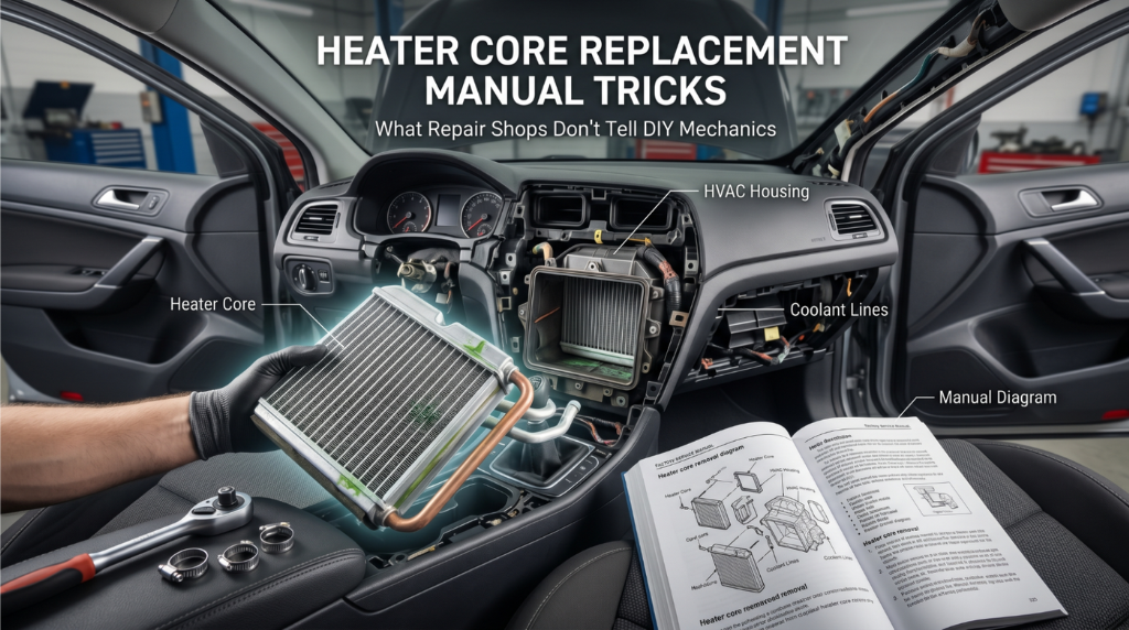
Heater Core Replacement Manual Tricks: What Shops Hide From Every DIYer

technician replacing heater core behind dashboard

Heater Core Replacement Manual Tricks can save you from a repair disaster that leaves coolant leaking inside your cabin or your engine running dangerously hot. Many DIYers rush into the job, crack fragile dash clips, and end up pulling the dashboard apart a second time.

The safest way to handle a heater core replacement is to follow factory manual procedures, use proven removal tricks, and pressure-test the system before reassembly. A few small steps can cut hours off the repair and prevent expensive interior damage.

This guide covers the best tips for heater core replacement, service manual shortcuts, dashboard removal tricks, coolant bleeding steps, and the common mistakes that quietly ruin most DIY repairs. You’ll also learn how to avoid leaks before the dash goes back in.

Heater Core Replacement Manual Tricks: The Real Procedure Behind the Dashboard

A technician using a specialized trim tool to safely remove a dashboard panel without breaking the plastic clips

Most DIYers underestimate how involved a heater core replacement actually is when done correctly. The core sits deep inside the HVAC housing, often buried behind the full instrument panel and dozens of fragile clips.

Without the right manual references and a few smart tricks, a single misstep can instantly double your job time.

This section covers the complete field-proven sequence from locating your exact OEM manual to pressure-testing the new core before reassembly.

Every step here reflects what experienced technicians actually do, not what a general repair guide summarizes in three vague sentences. Follow the sequence carefully, and this job gets done right the first time.

Step 1: Pull Your Factory Manual Before Touching Anything

Many failed heater core replacements start here, someone grabs the wrong guide and follows specs for a different trim level.

Your factory service manual contains vehicle-specific torque values, clip sequences, and coolant routing that generic sources simply don’t carry.

Finding your factory service manual PDF by VIN ensures every number you’re working from is OEM-accurate.

Key items to confirm in the manual before starting:

  • Heater core inlet and outlet hose routing paths
  • Dashboard harness disconnect sequence and connector locations
  • HVAC box removal torque specs and fastener count
  • Coolant drain volume and approved refill type
  • One-time-use clips that must be replaced, not reused

Skipping this step is the single biggest reason heater core replacements fail on the first attempt and require a redo.

Step 2: Read Exploded View Diagrams Like a Pro

A digital repair manual showing a detailed 3D exploded view diagram of a car's heater core and HVAC assembly

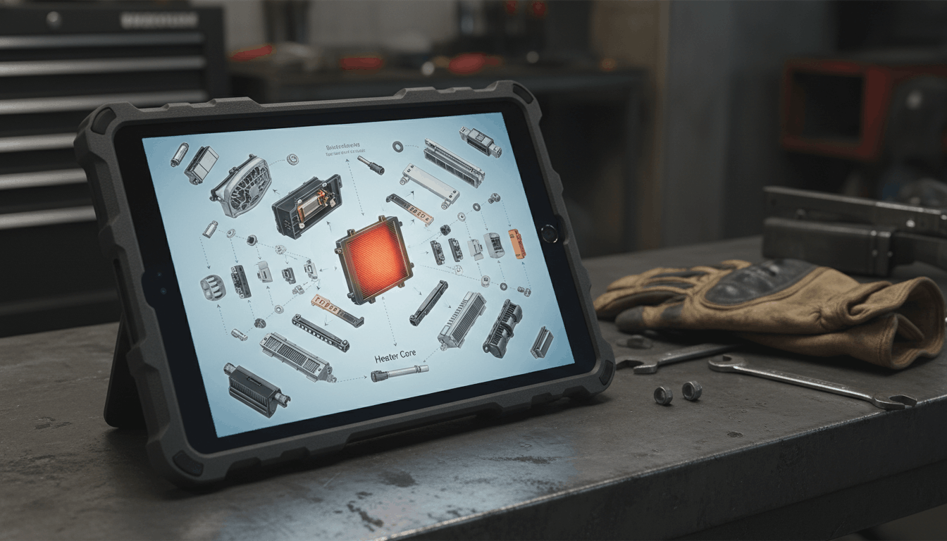
Your manual contains exploded-view diagrams that most people scroll past without a second glance. These visuals show the exact positions of every fastener, bracket, and clip in the disassembly order required by your vehicle.

Learning to read exploded view manual diagrams properly can cut your dashboard removal time by hours.

What to focus on in the diagrams:

  • Heater core housing clip positions and release directions
  • Coolant line bracket placements along the firewall
  • HVAC box bolt sequence for controlled removal
  • Electrical connector routing near the core housing
  • Any components requiring complete removal before access is possible

Treat the exploded view as your map throughout the entire job, follow it in order, and nothing gets guessed.

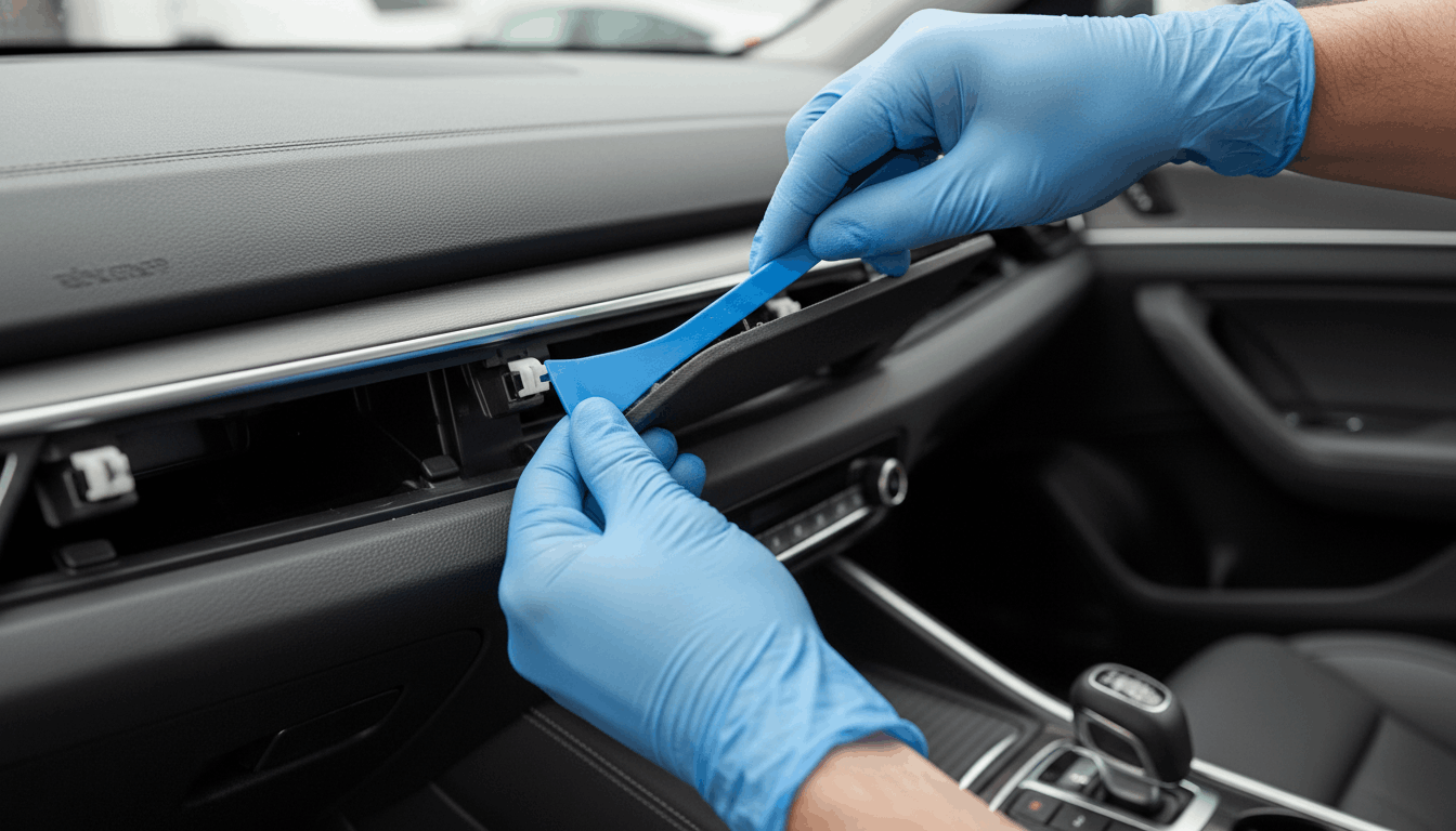
Step 3: Dashboard Access Tricks That Protect Clips

Organized car dashboard fasteners in labeled bags alongside plastic trim removal tools for a heater core job

Dashboard removal is where most heater core replacement jobs go sideways fast. Plastic clips crack under the wrong tool, harness connectors break under force, and trim panels snap when pulled out of sequence.

Before lifting the car for underhood coolant line access, confirm your safe jacking and lifting points from your manual to keep the job safe from the start.

Proven dashboard removal tricks from the field:

  • Use a dedicated trim clip removal tool, never a flathead screwdriver, on plastic
  • Work bottom to top, always remove lower trim before upper sections
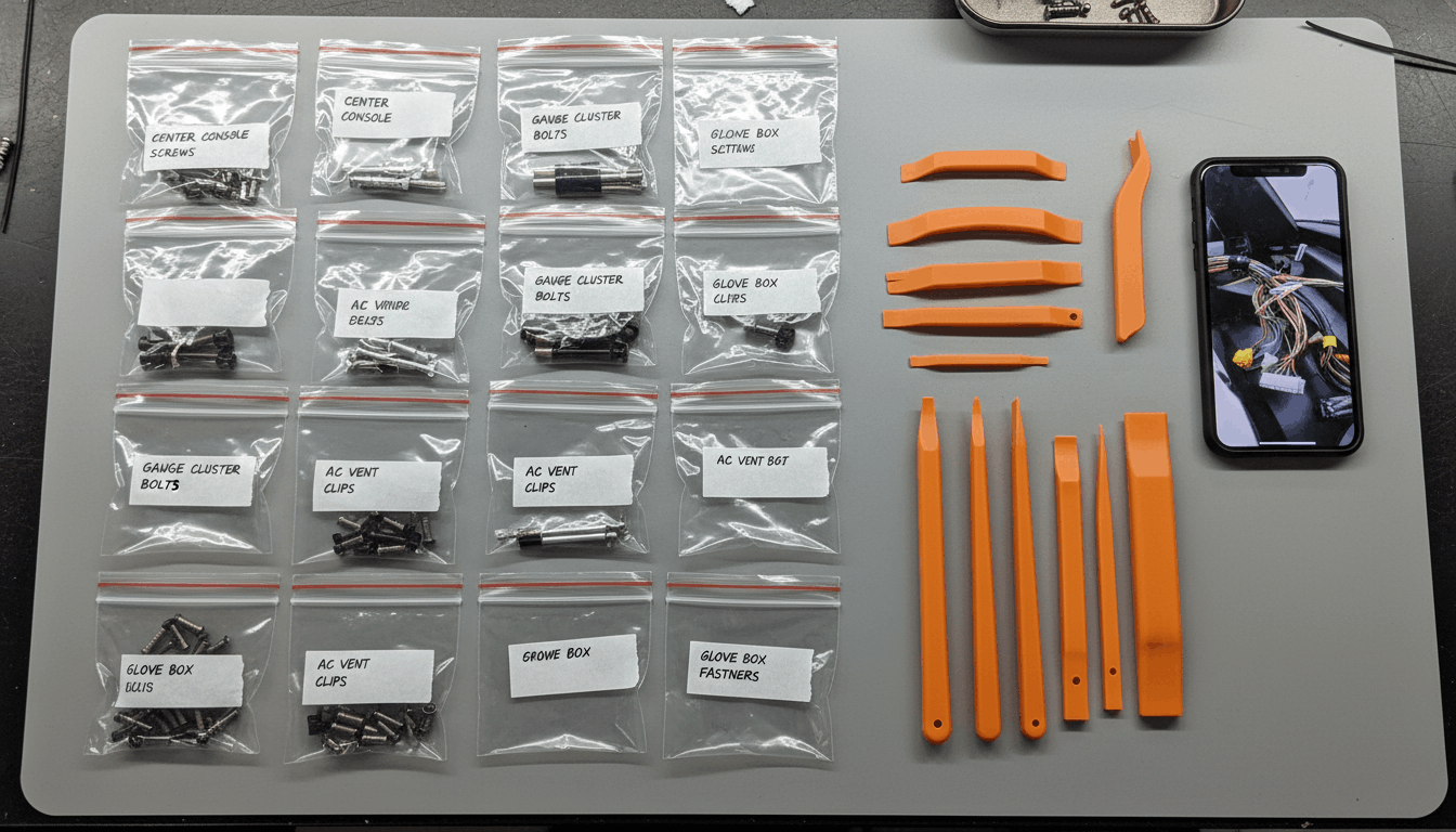
  • Label every harness connector with masking tape before disconnecting anything
  • Photograph every wiring cluster before you unplug a single connector
  • Sort all fasteners by location into labeled bags as you go

Rushing this step costs more time during reassembly than any shortcut actually saved.

Step 4: The Core Swap Steps Most Manuals Understate

A close-up of a new aluminum heater core being installed into the HVAC housing with new rubber O-rings visible

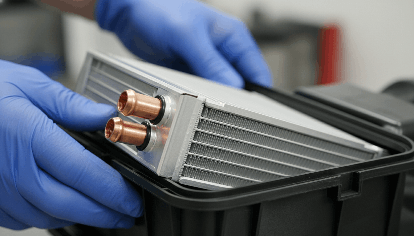
Once the HVAC box is accessible, the actual core replacement is manageable, but the manual often understates how tight the working clearances are.

The housing has very little room to maneuver, and forcing the core straight out damages fins and fittings. A slight twist before pulling is a field trick most written procedures never mention at all.

Task

Manual-Specified

Field Trick

Core removal direction

Straight pull

Slight twist left first

O-ring replacement

Sometimes optional

Always replace everyone

Hose clamp torque

Listed value

Add 10% for reused hoses

Pressure test

Not always listed

Always test to 15 PSI

Coolant fill sequence

Listed

Burp system before sealing

Always replace the O-rings on coolant line fittings regardless of what the manual says about reusability. Old O-rings fail under heat cycling within weeks of a freshly installed core, and the resulting leak means another full disassembly.

This one trick alone prevents the most common post-replacement comeback.

Step 5: Coolant Flush and Refill Done Right

After the new core is seated, a proper coolant flush and refill is not optional it’s the step that protects everything you just installed.

Pushing old, contaminated coolant through a brand new heater core shortens its life faster than most people realize.

Follow your vehicle’s specific coolant bleeding procedures to eliminate air pockets before you seal anything up.

Coolant refill checklist:

  • Use OEM-specified coolant type only, never a universal substitute
  • Fill slowly with the heater set to full heat to allow air to escape
  • Run the engine to operating temperature and monitor the reservoir level
  • Squeeze the upper radiator hose repeatedly to burp trapped air pockets
  • Top off the reservoir only after the thermostat fully opens

Never skip the bleed cycle. Air locks inside the core make it feel like the replacement failed entirely.

Step 6: Test Before Reassembling the Dashboard

A coolant system pressure tester showing 15 PSI to confirm no leaks in the new heater core before dashboard reassembly

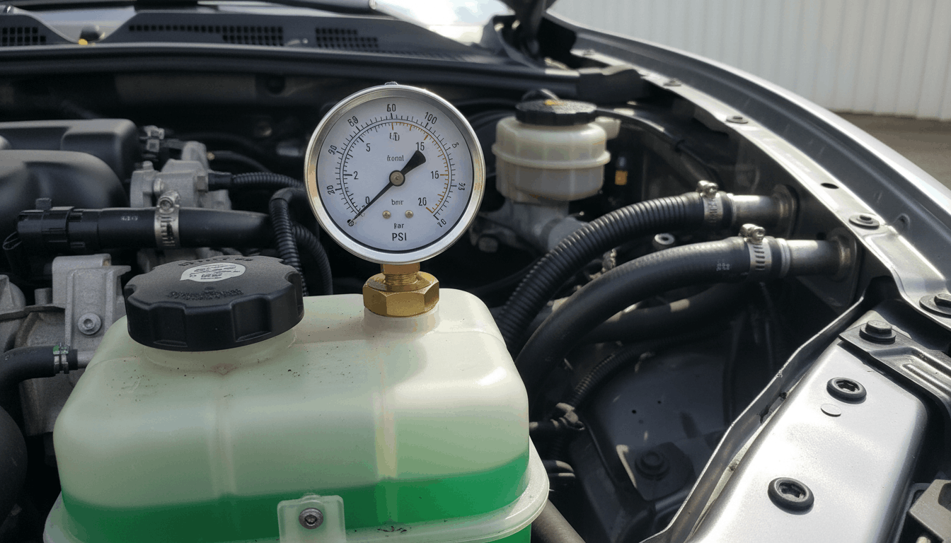
This is the trick most manuals skip entirely, and it’s the one that prevents the most frustrating comebacks. Before a single dashboard bolt is reinstalled, run a complete functional test of the heater core and HVAC system.

Anyone who has dealt with car overheating after a missed coolant leak knows exactly why catching it now matters far more than saving ten minutes.

Pre-reassembly test checklist:

  • Start the engine and let it reach full operating temperature
  • Check both coolant hose connections at the firewall for any seepage
  • Set the heater to maximum and confirm a warm, consistent air output
  • Inspect the firewall pass-through for moisture or drip marks underneath
  • Confirm the coolant reservoir level stays stable for at least 10 minutes

If everything checks out, reassemble the dashboard in the full reverse order of removal.

Conclusion

A clean heater core replacement comes down to following the manual tricks that field techs rely on every single time they do this job. From pulling OEM documentation before you start to reading exploded-view diagrams closely, removing the dash without breaking clips, and always testing before reassembly, every step builds on the last.

Do not rush the coolant bleed or skip the pressure test those two steps prevent most post-repair failures.

Follow the sequence here, work methodically with the right tools, and your heater core replacement will hold up for years without a revisit.

Frequently Asked Questions

A first-time DIY heater core replacement typically takes between 8 and 14 hours, depending on the vehicle layout and how well the dashboard clips cooperate.

Compact cars with densely packed dashboards routinely push toward the longer end of that range. Trucks and body-on-frame vehicles tend to give easier access and shorter total time.

Having your factory service manual open throughout the entire job is the single biggest time-saver. Budget a full weekend for your first attempt so no phase gets rushed and no clip gets forced.

A bypass hose loop is a temporary workaround where both the coolant inlet and outlet lines are connected directly to each other, cutting the core out of the circuit entirely. It stops the coolant leak and temporarily protects the cabin from vapors.

This fix eliminates all cabin heat as a trade-off and should never be treated as a permanent solution. The underlying heater core replacement still needs to happen, ideally within a few weeks. Driving long distances with the core bypassed stresses other parts of the cooling system over time.

The most common cause of early failure after a heater core replacement is pushing degraded coolant through a new unit without first flushing the system.

Old coolant carries rust scale, silicate deposits, and a pH imbalance that corrode the new core from day one. Using the wrong coolant type for your vehicle significantly speeds up that process.

Air pockets left in the system after refilling also create localized overheating inside the core housing. Following the OEM-specified coolant bleeding procedures after installation is the most direct way to protect the replacement in the long term.

A faint coolant smell immediately after a heater core replacement can be due to residual fluid on interior surfaces during disassembly. That should clear in 1 to 2 drives with the windows open. A persistent sweet smell after several drives points to an active leak at one of the coolant line connections at the firewall.

This almost always means an O-ring was not fully replaced or a hose clamp was not seated properly during the core installation. Catch it early, tighten or re-seat the fitting, and recheck during a warmup cycle before buttoning the dashboard back down.

A mildly clogged heater core can sometimes be cleared with a targeted flush using low-pressure water flow in reverse through the coolant lines.

This works when the blockage is soft scale or loose debris from old coolant breakdown. Hard mineral deposits or internally corroded passages do not respond well to flushing and typically require a full replacement.

The clearest way to tell the difference is a pressure test if the core holds pressure but heat output is weak, a flush is worth attempting first. If pressure drops or the core shows external damage, skip straight to replacement and save the labor time.

Posted on

Clutch Replacement Flywheel Torque Specs: What One Wrong Number Can Cost You

Mechanic tightening flywheel bolts with torque wrench during clutch replacement in workshop

Getting your clutch replacement right starts and ends with the flywheel torque specs. Miss them, and you’re looking at a warped flywheel, a destroyed pressure plate, or worse, bolts backing out at highway speed. These are not the kind of mistakes you want to make twice.

Typically, flywheel-to-crankshaft bolts require 44–96 ft-lbs and pressure plate bolts 13–35 ft-lbs, applied in star patterns and multiple passes. Passenger vehicles often range from 55–105 ft-lbs depending on engine type. Performance engines may exceed 88 ft-lbs. Always use new bolts and threadlocker.

This guide covers the exact torque specs by vehicle type, the correct tightening sequence, bolt prep, and the most common mistakes that send people back to the shop.

Clutch Replacement Flywheel Torque Specs: The Numbers That Actually Matter

technician torquing flywheel bolts in star pattern during clutch installation

Most guides throw out one number and call it done. That’s not how this works. Flywheel torque specs vary by engine family, bolt grade, and flywheel type, and getting the right number for your specific application is the only thing that matters here.

The table below covers the most commonly searched vehicles and platforms. Cross-reference this with your factory service manual PDF by VIN before you put a wrench on anything. OEM specs are always the authority.

Flywheel Bolt Torque Reference by Platform

Vehicle / Platform

Flywheel-to-Crank (ft-lbs)

Pressure Plate (ft-lbs)

Passes

GM LS1 / GTO

74 (in 3 passes: 15, 37, 74)

52 (in 4 passes: 7, 18, 30, 52)

Multi-pass

Ford SBF 289/302

75–85

18–24

2–3 passes

BMW E46 325xi

77 ft-lbs (105 Nm)

16 ft-lbs (22 Nm) + 90°

Angle torque

Audi Dual-Mass

44 ft-lbs (60 Nm) + 90°

16 ft-lbs (22 Nm) + 90°

Angle torque

Honda Prelude (H22)

76

19

Star pattern

Volvo S60R M66

33 ft-lbs + 65°

22

Angle torque

Toyota RAV4 (1AZ)

96

18–22

Crisscross

Geo Metro / Suzuki

54–57.5

13.5–20

Star pattern

Mitsubishi DSM (4G63)

94–101 (in 3 steps: 60, 80, 100)

14–17

Star pattern

Chevy Big Block 454

60 (75 with ARP bolts)

35

Star pattern

SVT Focus / Cobra

63

33 ft-lbs + 60°

Angle torque

Important: Always verify against your specific year, engine code, and transmission variant. These numbers are general references; they are not a substitute for your OEM service manual.

Why Torque Sequence Matters as Much as the Number

technician tightening flywheel bolts in star pattern using torque wrench during clutch install

Many techs focus solely on the torque value and skip the sequence. That’s a mistake.

Tightening flywheel bolts in a single pass or random order creates uneven clamping force. On a rotating mass spinning thousands of times per minute, that imbalance becomes a real problem fast. Vibration, stress cracking, and eventually bolt fatigue are what follow.

Here is the correct approach for flywheel bolt installation:

  • Clean the bolt threads and crankshaft holes thoroughly before installation
  • Apply thread sealant (not just Loctite) on bolt holes that open into the crankcase, common on Ford 289/302 engines
  • Use red Loctite on flywheel-to-crank bolts, given the high rotational forces involved
  • Tighten in a star or crisscross pattern, working across the bolt circle diagonally
  • Never reach final torque in one pass, use at least two passes, three for multi-pass specs like GM LS platforms
  • For angle-torque specs (like Audi and BMW applications), use an angle gauge, not guesswork

The 6-bolt flywheel sequence goes: 12 o’clock, 6 o’clock, 2 o’clock, 8 o’clock, 4 o’clock, 10 o’clock. That 180-degree opposing pattern is the correct one for even seating.

Pressure Plate Torque Steps You Cannot Skip

technician tightening clutch pressure plate bolts evenly in crisscross pattern with torque wrench

The pressure plate bolts are frequently undertorqued because they look small. Do not let that fool you.

An unevenly torqued pressure plate will warp the diaphragm spring, cause premature clutch disc wear, and produce the classic shudder on engagement. Here is how to do it right:

  • Install all bolts finger-tight first before touching the torque wrench
  • Tighten in quarter-turn increments, rotating around the bolt circle evenly
  • Never tighten one bolt to full torque before the others are snugged; you will crack or warp the cover
  • Final torque typically falls between 13 and 35 ft-lbs, depending on the platform (see table above)
  • On angle-torque platforms, the initial Nm value plus the final degree turn is required, not optional
  • Blue Loctite on pressure plate bolts is acceptable on most platforms; avoid red here as future serviceability matters

For platforms using a dual-mass flywheel, always replace the flywheel bolts; they are torque-to-yield and not reusable. This is a step that catches first-timers off guard. The same rule applies to many angle-torque flywheel bolts on European platforms.

Single-Mass vs Dual-Mass Flywheel Torque Differences

technician comparing single-mass and dual-mass flywheel torque installation methods in workshop

The flywheel type in your vehicle affects more than just NVH. It changes how you torque the assembly.

Single-mass flywheels use a straightforward torque-to-value spec. You torque the bolts to a number, verify in the star pattern, and done. Most domestic and older import platforms use this setup.

Dual-mass flywheels are common on modern European vehicles and many turbo applications. Key differences include:

  • Bolts are torque-to-yield and must be replaced every time
  • Torque specs often combine an initial Nm value plus an angle turn (e.g., 60 Nm + 90°)
  • The assembly is more sensitive to uneven torquing due to internal damper springs
  • Mixing single-mass and dual-mass specs is one of the fastest ways to cause a failure

If your vehicle came with a dual-mass flywheel and you are converting to a single-mass unit for performance reasons, confirm the bolt spec with your clutch kit manufacturer directly. The specs will often differ from OEM.

For reference on how torque values relate across drivetrain components, the guide on engine torque specs for cylinder heads follows the same multi-pass logic used here. It is worth reading alongside this one.

Common Flywheel and Clutch Torque Mistakes

technician correcting clutch flywheel installation mistakes in workshop with torque wrench and alignment tools

These are the errors most often seen in service bays after a DIY clutch job goes wrong.

  • Using internet forum numbers without verifying against OEM specs, always double-check with your genuine OEM workshop manual
  • Applying Loctite to angle-torque bolts can create a false torque reading by reducing thread friction
  • Reusing torque-to-yield bolts, they stretch on first use and cannot be relied on a second time
  • Skipping the clutch alignment tool, the disc will shift during pressure plate torquing and cause binding on installation
  • Torquing the flywheel without locking the crankshaft leads to inconsistent readings and false torque values
  • Confusing ft-lbs with Nm, 60 Nm is only 44 ft-lbs; treating them as the same number is a serious over-torque on smaller bolts

Also, if you replaced the transmission recently, double-check the transmission fluid capacities in the manual before finishing the job. Low fluid after a clutch replacement is a common oversight.

Tools Required for Accurate Torque

Getting the specs right only matters if your tool is accurate.

  • Calibrated click-type torque wrench, borrow or buy one, do not use an impact gun for final torque
  • Angle gauge adapter required for any angle-torque specification
  • The flywheel locking tool prevents the crank from rotating during torquing
  • The clutch alignment tool must match the disc spline count for your transmission input shaft
  • Thread prep tools: wire brush, thread chaser, brake cleaner for cleaning bolt holes

A torque wrench that has never been calibrated is not meaningfully better than a breaker bar. If you are serious about this job, verify your wrench or rent a calibrated unit from a parts store.

Torque Spec Summary Visual

Component

Low End

High End

Pattern

Flywheel-to-Crank Bolts

44 ft-lbs

101 ft-lbs

Star / Multi-pass

Pressure Plate Bolts

13 ft-lbs

52 ft-lbs

Star / Incremental

Angle-Torque Add-on

+60°

+90°

After initial Nm

When done correctly, a clutch replacement paired with precise flywheel torque specs will give you smooth, reliable power transfer for the full life of the parts. Cut corners here, and you will be pulling the transmission again sooner than expected.

If your vehicle had timing-related work done alongside this job, the guide on timing belt replacement assembly sequencing is a useful companion resource for keeping the full drivetrain assembly correct.

Frequently Asked Questions

It depends on the platform. For most domestic engines, such as GM and Ford applications, red Loctite on flywheel-to-crankshaft bolts is recommended because the bolt holes pass through to the crankcase, and the thread sealant doubles as a leak-prevention measure.

On European vehicles with angle-torque specifications, Loctite can affect friction coefficients, leading to inaccurate torque readings. Always check your OEM service manual first. Some factory bolts come pre-coated with a yellow or silver thread-locking compound, meaning additional Loctite is not required.

When in doubt, use the OEM-specified fastener and follow the spec as written. Reusing old bolts without fresh thread treatment is one of the most common causes of early flywheel bolt loosening after a clutch job.

On many modern vehicles, flywheel bolts are torque-to-yield fasteners, meaning they stretch permanently during initial installation and cannot safely be reused. This is especially true on European platforms like BMW, Audi, and Volvo with angle-torque specifications.

Using a stretched bolt a second time risks under-clamping or outright failure at speed. Domestic platforms with standard hex bolts are generally reusable if the bolts show no deformation, but replacing them remains the safer practice. 

Always check your vehicle-specific service data. The cost of new flywheel bolts is minimal compared to the labor cost of a repeat clutch job caused by a backed-out bolt.

Overtorquing flywheel bolts can stretch or snap the bolt, strip the crankshaft threads, or crack the flywheel flange. On smaller-displacement engines using 14mm bolts, the margin between correct torque and failure is surprisingly small.

A snapped bolt inside the crankshaft requires either a bolt extractor or full engine disassembly in severe cases. Overtorquing is more common when mechanics skip multi-pass procedures and go straight to the final torque in one shot. Always use a calibrated torque wrench and follow the correct sequence.

If you suspect a bolt has been overtorqued, inspect it for visible stretch or thread distortion before reassembly.

Yes, significantly. ARP bolts are made from higher-grade material than OEM fasteners and are typically torqued 15 to 20 percent higher than stock specifications.

For example, a Chevy 350 OEM flywheel spec of 60 ft-lbs becomes 75 ft-lbs with ARP hardware. ARP also recommends using their Ultra-Torque moly lubricant on the threads and under the bolt head, which changes the friction coefficient and affects how torque translates to clamping force.

Do not apply ARP specs to OEM bolts or vice versa. Always follow the spec sheet included with your ARP fastener kit, as values can vary by application, engine family, and whether the holes are blind or through-holes.

The most common symptoms of uneven pressure plate torque are clutch shudder on engagement, vibration felt through the pedal at low speed, and premature disc wear on one side.

In some cases, a warped pressure plate diaphragm produces a pulsing feel when pressing the clutch pedal, almost like a slight catch or release variation at the same pedal position every time.

If you notice these symptoms shortly after a clutch replacement, the cause is often an uneven torque sequence or missing the quarter-turn incremental tightening step. 

A visual inspection may show that one side of the disc has more contact wear than the other, confirming uneven clamping pressure across the assembly.