Posted on

Safe Hybrid High-Voltage Disconnect Steps: What Most Techs Get Wrong

Technician safely disconnecting hybrid high-voltage battery service plug

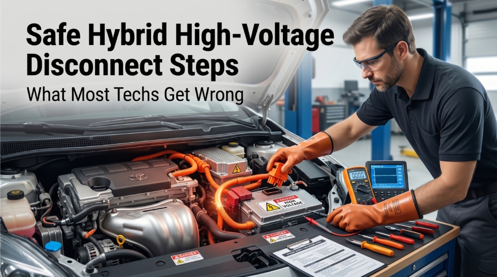
Working on a hybrid vehicle without following safe high-voltage disconnect procedures is potentially fatal. Battery packs in modern hybrids reach 144 to over 800 volts, rendering standard shop gloves useless.

Strictly following the sequence of ignition shutdown, 12V battery isolation, and service plug removal, while wearing insulated gloves, is vital. A mandatory 10-minute wait for capacitor discharge, followed by voltage verification, is essential to prevent life-threatening accidents during repairs.

This article walks through every step of a proper hybrid high-voltage disconnect, the PPE you need, model-specific differences, and the verification test most shops skip.

Safe Hybrid High-Voltage Disconnect Steps: The Full Procedure Most Guides Leave Incomplete

technician testing abs module power supply voltage with multimeter

This isn’t a casual checklist. The following guide is based on OEM emergency response procedures, NATEF-recognized protocols, and real workshop practice. It covers what to do before, during, and after the disconnect. Every step matters.

Why the Risks Are Bigger Than You Think

Before diving into the steps themselves, the danger needs to be clear. Many technicians treat hybrid work like a regular 12V service. That mindset is where things go wrong.

Hybrid battery packs operate at lethal voltages. The 1st-gen Toyota Prius runs at 273.6V. Later models hover around 201–207V. Plug-in hybrids and newer systems from Honda, Volvo, and Ford push 400–800V in some configurations. Compare that to a standard household outlet at 120V, and you get a sense of what’s at stake.

There are three main risks to understand:

  • Electric shock: Even without visible sparks, contact with an energized HV circuit can stop your heart.
  • Arc flash: Disconnecting under load creates a flash intense enough to cause severe burns and ignite nearby materials.
  • Component damage: Battery packs cost tens of thousands of dollars. Improper disconnection can destroy them instantly.

The key term techs use is “safe down”, which means fully de-energizing the vehicle before any HV work begins.

PPE You Must Have Before Touching Anything

Skipping PPE because “it’ll be quick” is exactly when injuries happen.

Before starting any high-voltage disconnect procedure, gather the following:

  • Class 0 rubber insulating gloves (rated to 1,000V minimum, currently certified)
  • Leather over-gloves worn on top for puncture protection
  • Safety glasses or a face shield
  • High-voltage-rated multimeter (CAT III or CAT IV rated)
  • Insulated tools rated for HV work

Inspect your gloves every single time before use. Check for pinholes by rolling the cuff and trapping air inside. A small hole in a rubber glove near live HV terminals is the same as wearing nothing.

PPE Item

Minimum Rating

Purpose

Rubber insulating gloves

Class 0 / 1,000V

Shock protection

Leather over-gloves

ANSI/ISO compliant

Puncture/abrasion protection

Safety glasses

ANSI Z87.1

Arc flash eye protection

Multimeter

CAT III/IV

Voltage verification

Insulated tools

1,000V rated

Safe component handling

Step 1: Power Down and Remove the Key

This is the starting point of every safe hybrid service procedure.

Turn the ignition to OFF and physically remove the key from the switch. If the vehicle uses a keyless start system, press the power button to shut it down, then remove the key fob from the vehicle entirely. Keep it at least 15 feet away.

Why does fob distance matter? Because proximity-sensing systems can re-energize the high-voltage circuit even with the ignition off. Some Toyota and Lexus hybrids are known for this behavior. You don’t want the car “waking up” while you’re in the middle of a procedure.

  • Confirm the READY indicator is fully off on the dash
  • Do not assume the vehicle is off just because the engine isn’t running
  • Hybrids in “Ready” mode are silent and still fully energized

Step 2: Disconnect the 12V Auxiliary Battery First

technician disconnecting hybrid vehicle 12v battery safely

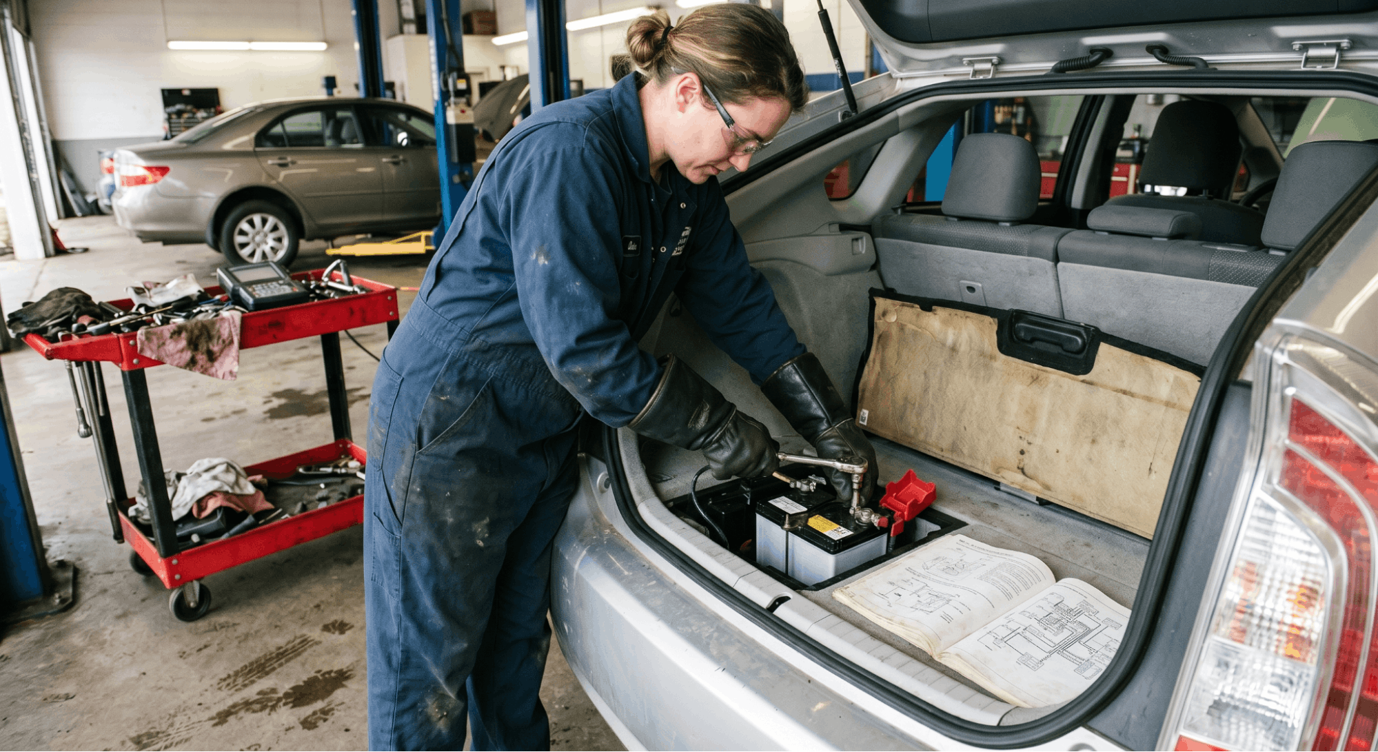
This step is the one most guides bury or skip entirely. It’s actually critical.

The 12V battery controls the contactors (relays) that connect the high-voltage pack to the rest of the vehicle. Disconnecting it first ensures those contactors stay open. Without this step, even a properly removed service plug may not fully isolate the HV system in every model.

Disconnect the negative terminal first, then the positive. Wrap the terminal ends in electrical tape or use a non-conductive cover to prevent accidental re-contact.

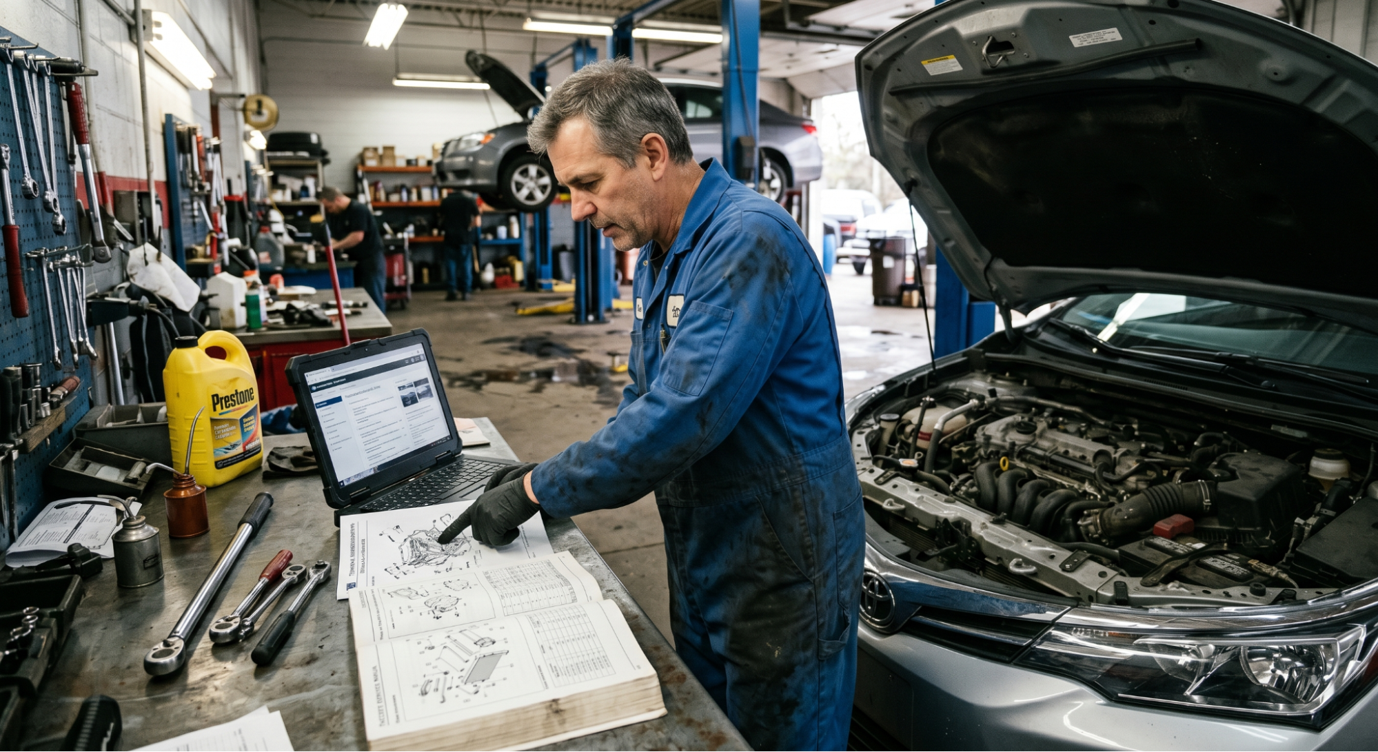
On some hybrids (such as the 2004+ Toyota Prius), the 12V battery is in the trunk rather than under the hood. Check the vehicle’s factory service manual for the exact location. If you’re not sure where to find it, resources like Find Your Factory Service Manual PDF by VIN can point you in the right direction.

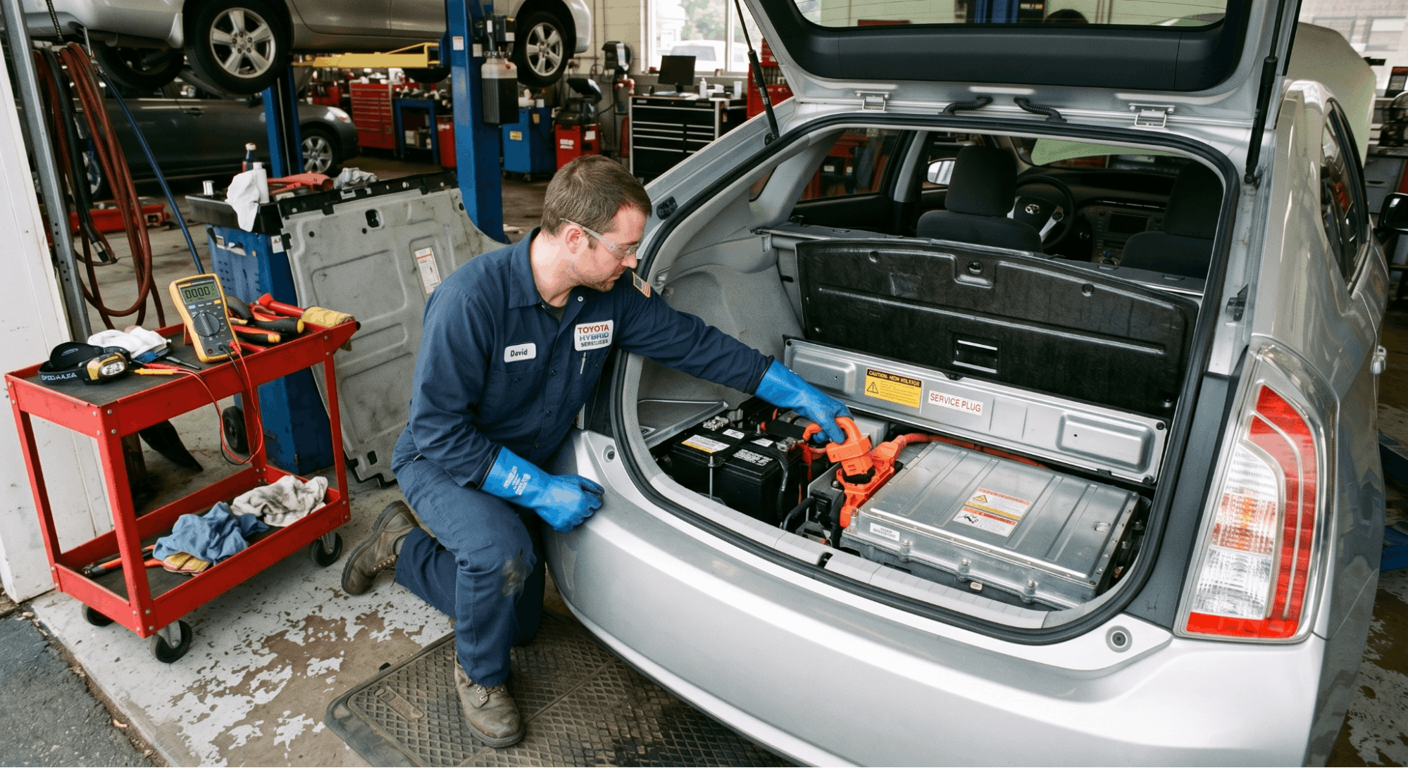
Step 3: Locate and Remove the Service Disconnect Plug

Now comes the core of the hybrid high-voltage disconnect procedure.

Every hybrid has a manual service disconnect (MSD), sometimes called a service plug or safety switch. It’s designed specifically to break the HV circuit. These are typically bright orange and marked with a yellow high-voltage warning triangle.

Common service disconnect locations by model:

Vehicle

Disconnect Location

Disconnect Type

Toyota Prius (Gen 1)

Trunk, left front corner

Orange pull-out plug

Toyota Prius (Gen 2+)

Trunk, left side

Lever-style pull plug

Honda Civic Hybrid

Behind rear seat, small cover

Flip switch DOWN to OFF

Honda CR-V Hybrid

Under rear cargo area carpet

Rotary switch

Volvo T8 / XC60 / XC90

Rear seat transmission tunnel

Orange jumper with lever

Ford Escape Hybrid

Trunk, under liner

Orange-handled plug

Chevy/GMC Hybrid Pickup

Under rear passenger seat

Green rotary switch

Put on your Class 0 gloves before touching the MSD. Pull or rotate as specified. Once removed, place the plug on a workbench away from the vehicle. Lock or cover any exposed MSD socket to prevent debris ingress or accidental re-insertion.

Step 4: Wait. Don’t Skip This Part.

technician waiting for hybrid inverter capacitor discharge

The capacitors inside the hybrid’s inverter and power electronics retain charge after the service plug is removed. These components can hold dangerous voltage even with the pack disconnected.

Wait a minimum of 10 minutes. Some manufacturers specify 15 minutes. Don’t fill this time by poking around the engine bay.

This discharge period is non-negotiable. The capacitors supply power to the power inverter and motor drive systems. Touching HV terminals during discharge is exactly as dangerous as touching them before the disconnect.

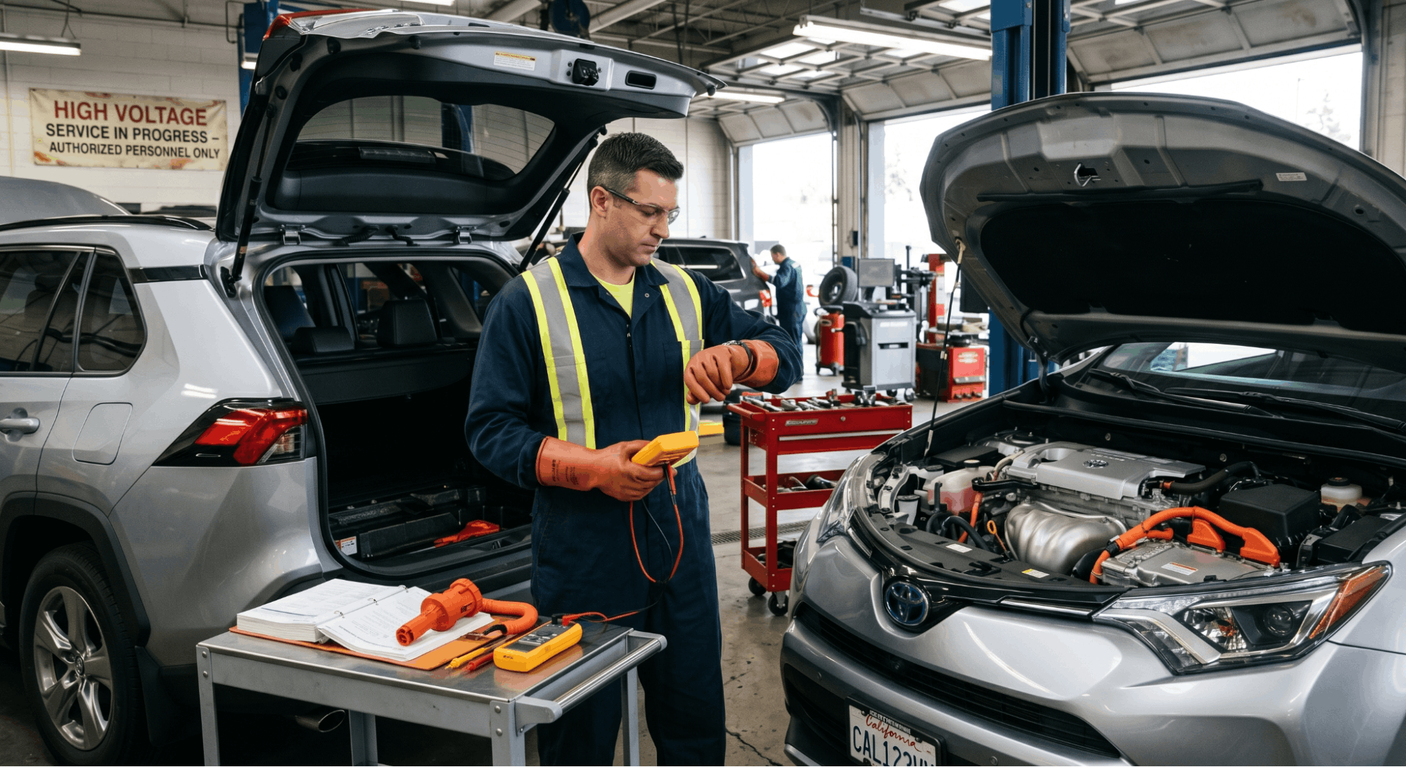
Step 5: Verify with a Live-Dead-Live Test

Once the wait period is done, you still don’t assume the system is safe. You verify it.

This is the Live-Dead-Live test, and it’s the professional standard for confirming an HV system is de-energized:

  1. Live check: Touch your multimeter leads to the 12V battery terminals. Confirm it reads 12V. This proves your meter is working correctly and on the right scale.
  2. Dead check: Wearing HV gloves, remove the power inverter cover to access the HV terminals. Test the voltage between the HV positive and negative terminals. It must read 0 volts.
  3. Live check again: Retest your multimeter on the 12V battery to confirm the meter is still functional.

If the dead check shows anything above 0V, do not proceed. The system has not fully discharged, or there’s a fault in the HV circuit.

This three-step verification is what separates technicians who actually know high-voltage safety from those who assume they do. You can cross-reference this approach with OEM vs. Aftermarket Manuals: Best for DIY if you’re working from aftermarket documentation and want to understand when factory guidance matters most.

Model-Specific Notes Worth Knowing

technician accessing Prius hybrid service plug location

Each manufacturer handles the hybrid high-voltage disconnect slightly differently, and the details matter.

Toyota/Lexus: Most models have a service plug in the trunk or rear cargo area. The 2nd-gen Prius requires removing the trunk floor panel before accessing the 12V battery. Always confirm the “READY” light is off before proceeding.

Honda: Older Civic hybrids use a flip switch behind the rear seat. The Accord Hybrid uses a service plug under the cargo area. Honda also specifies removing a specific main fuse in some models to fully isolate the HV system.

Ford Escape / Mariner / Tribute Hybrids: These used an “inertia switch” in early models that auto-disconnected during collisions. However, this does not mean the HV system is always safe after an impact. Always perform a full manual disconnect regardless.

Volvo (T8, Recharge): The orange MSD jumper sits under a cover on the transmission tunnel (SPA/P5 platform) or in the right rear footwell (CMA/P6). A green locking tab must be lifted before the lever can be raised to remove the plug.

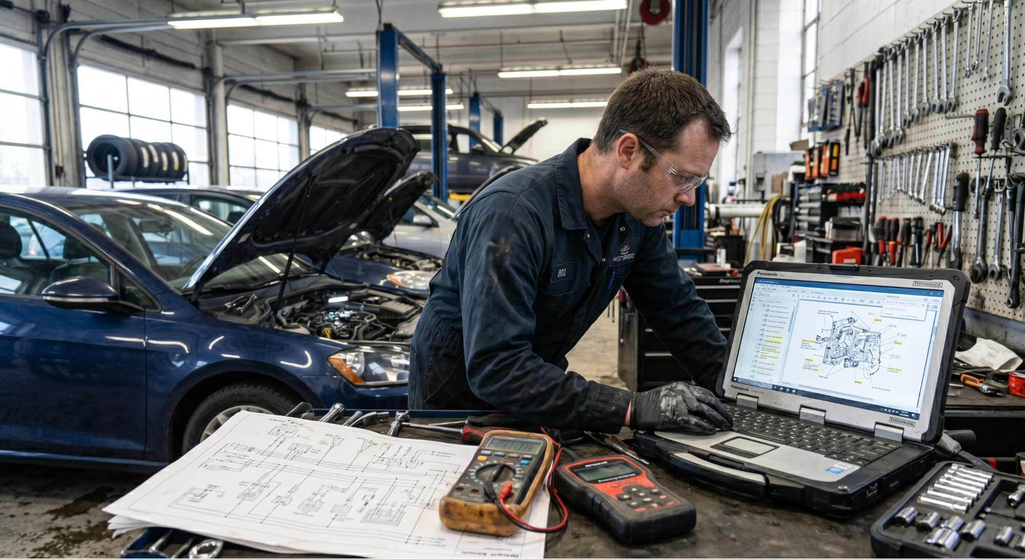
If you need model-specific torque specs or wiring diagrams alongside your service work, it’s worth knowing when to upgrade to a Factory Service Manual since HV procedures in aftermarket guides often lag behind OEM updates.

Reconnection: The Reverse Sequence Matters Too

Incorrectly reconnecting the system can damage expensive HV electronics. Follow the reverse order:

  1. Reinstall the service disconnect plug firmly until it locks
  2. Reconnect the 12V battery (positive first, then negative)
  3. Return the key fob or key to the vehicle
  4. Start the vehicle and verify the READY status
  5. Clear any stored codes and re-initialize systems like power windows if needed
  6. Test drive to confirm normal operation

Some hybrid systems automatically set codes whenever the HV system is disturbed. Clear them, drive, and recheck. If codes return, there’s an underlying issue to diagnose.

A Quick Word on Documentation

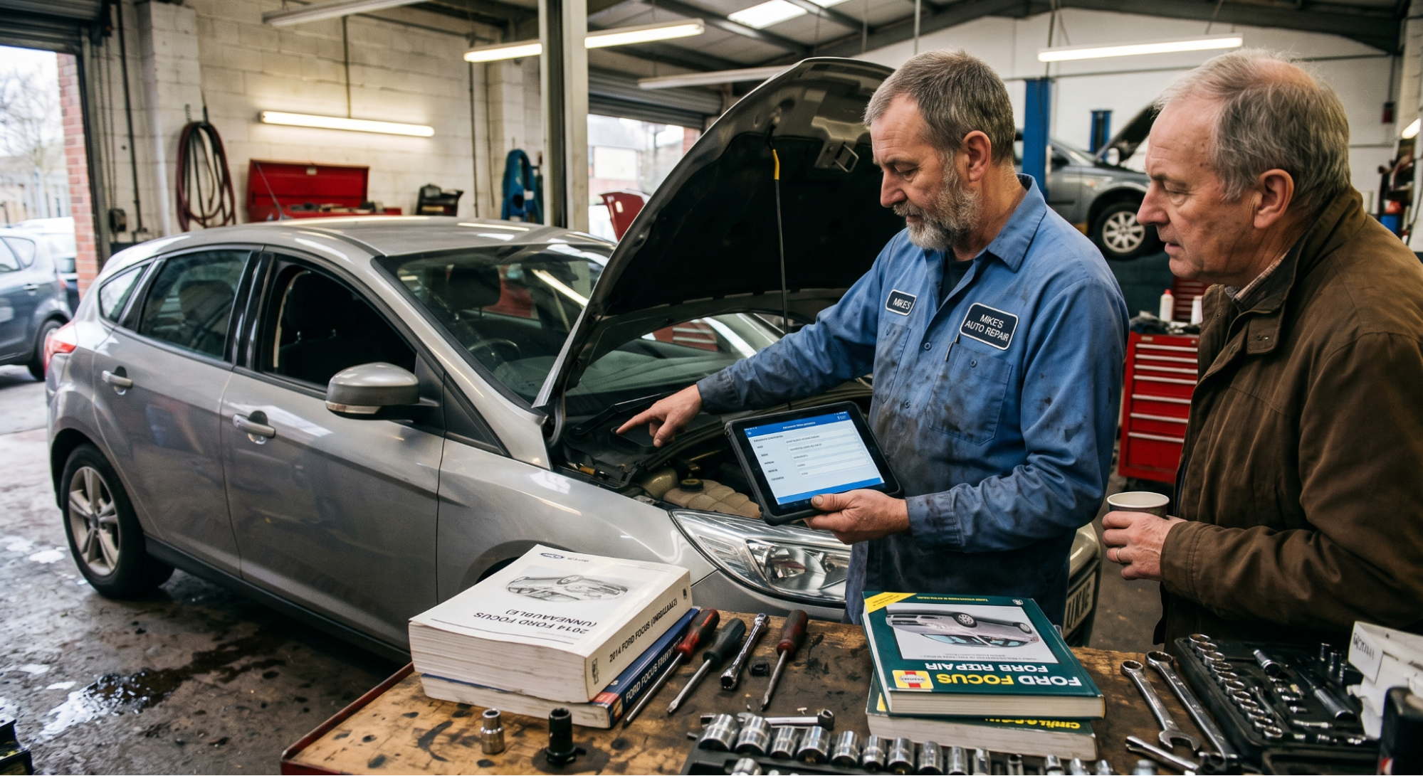
Working from a generic guide is fine for learning the concept. But when you’re actually servicing a specific vehicle, the OEM manual is the only acceptable source. High-voltage systems vary enough between model years that a 2008 procedure can be wrong for a 2016 version of the same car.

If you don’t have access to the right manual, Where to Download Genuine OEM Workshop Manuals is a useful place to start. And for any free online sources, it’s always worth checking whether Free Online Car Repair Manuals Are Safe before relying on them for HV work specifically.

Wrapping It Up

The safe hybrid high-voltage disconnect process isn’t complicated once you know it. But it has zero tolerance for shortcuts. Turn the ignition off, remove the key fob from range, isolate the 12V battery, locate and remove the service plug with rated insulated gloves, wait for capacitor discharge, and verify zero volts before touching anything else.

The technicians who have had close calls on hybrid high-voltage systems almost always skipped one of those steps. The sequence exists for a reason. Follow it every time.

Frequently Asked Questions

Yes, and this is one of the most underestimated risks in hybrid service work. A hybrid in “Ready” mode is fully energized even when the combustion engine is off. The vehicle runs silently on electric power, and the high-voltage system is live.

Even after a proper shutdown, the capacitors inside the inverter retain dangerous charge for up to 15 minutes. “Looks off” is not a safe standard. The only safe standard is a completed disconnect procedure followed by a confirmed 0-volt reading on a multimeter. Always treat the system as live until the Live-Dead-Live test proves otherwise.

Orange cables on a hybrid carry the full high-voltage supply from the battery pack to the motor, inverter, and other HV components. Contact with these cables while energized can deliver anywhere from 144 to 800 volts, depending on the vehicle.

That level of voltage and current is fatal in most exposure scenarios. Even briefly touching an orange cable while the hybrid system is active is not survivable.

The orange color is a universal industry warning. If you see orange, treat it as live until the entire safe-down procedure is completed and verified.

No. The service disconnect location varies significantly by manufacturer and even by model year. Toyota and Lexus typically place it in the trunk or rear cargo area. Honda uses either a flip switch or a fuse, depending on the model. Volvo T8 hybrids have the MSD on the rear seat transmission tunnel.

Chevy and GMC hybrid trucks put the rotary switch under the rear passenger seat. There is no universal location. Always consult the specific vehicle’s factory service manual before starting any high-voltage disconnect procedure, even if you’ve worked on a similar model before.

Most manufacturers specify waiting at least 10 minutes after removing the service plug before touching any high-voltage components. Some, like Toyota on certain Prius generations, recommend up to 15 minutes.

This waiting period allows the capacitors in the power inverter and drive system to fully discharge. Touching HV terminals during this window is still dangerous. The wait time is non-negotiable.

After the wait, always perform a Live-Dead-Live test with a high-voltage-rated multimeter to confirm that the system reads 0 volts before proceeding with any repair.

Standard latex or mechanic’s gloves are not rated for hybrid high-voltage work. You need Class 0 rubber insulating gloves rated to a minimum of 1,000 volts. These should also carry a current certification date since rubber degrades over time and can develop micro-cracks that aren’t visible.

Most professionals also wear leather overgloves over the rubber insulating gloves for added puncture and abrasion protection. Before each use, inspect the rubber gloves by rolling the cuff and trapping air inside to check for pinhole leaks. A defective glove near an energized HV circuit is the same as no protection at all.

Posted on

Transmission Limp Mode & Solenoid Testing: What the Code Isn’t Telling You

Technician testing transmission solenoid with multimeter

Avoid replacing parts immediately when a transmission enters limp mode. Replacing a solenoid without proper testing often leads to recurring failures caused by contaminated fluid, wiring damage, or a faulty TCM.

Prevent misdiagnosis by determining if the fault is electrical, mechanical, or fluid-based. Limp mode, which typically restricts the gearbox to 2nd or 3rd gear, can be diagnosed by checking for 5–30 ohms of resistance and verifying a mechanical “click” with 12V power.

This guide explains the complete transmission and solenoid diagnostic process, from initial code reading to final repair verification.

Transmission Limp Mode & Solenoid Testing: Why One Code Has Three Different Root Causes

technician diagnosing transmission solenoid electrical fault

Limp mode triggers when the TCM detects severe faults, locking the gearbox in second or third gear to prevent damage. While codes P0750–P0770 pinpoint an affected solenoid circuit, they do not specify the cause of failure.

Accurate repair requires identifying which of three failure paths is responsible. Distinguishing between these paths ensures the correct tools and tests are used, preventing misdiagnosis and recurring issues.

Step 1: Read the Fault Code Category Before Anything Else

The DTC description is more useful than most people realize. The exact wording tells you which test to run first and saves significant time before touching the transmission.

Solenoid DTCs follow a specific pattern:

Code Range

Circuit Affected

Fault Type Indicated

P0750-P0770

Shift Solenoids A, B, C

Electrical circuit malfunction

P0960-P0972

Pressure Control Solenoids

Electrical or range/performance fault

P0776-P0798

Pressure Control Solenoids

Out of range / mechanical stuck

P0841-P0848

Transmission Fluid Pressure Sensor

Pressure circuit fault

Notice the distinction: codes ending in ‘electrical circuit fault’ point to wiring, connectors, or the TCM before the solenoid itself. Codes ending in ‘range’ or ‘performance fault’ point to the solenoid’s mechanical operation or fluid condition.

Pull the full freeze frame data alongside the fault code. Check engine RPM, vehicle speed, transmission temperature, and commanded versus achieved gear at the moment of fault. This data indicates whether the fault occurred under specific load conditions, narrowing the failure to a particular shift event rather than a general system fault.

For sourcing the correct factory-documented resistance specifications and wiring diagrams for your specific vehicle, having reliable access to OEM documentation matters far more than generic online specs. This guide on Where to Download Genuine OEM Workshop Manuals covers the most trusted sources currently available.

Step 2: Test the Wiring and Connector Before Removing Anything

mechanic testing transmission solenoid wiring harness

The majority of solenoid fault codes on high-mileage vehicles trace back to the wiring harness or the transmission connector, not the solenoid itself. This is particularly common on GM, Ford, and Chrysler platforms, where the external harness runs close to the exhaust and can degrade over time due to heat-related insulation issues.

Before dropping the transmission pan, run these external checks:

  • Disconnect the transmission harness connector and inspect every terminal for corrosion, pushed-back pins, or moisture damage
  • Measure the supply voltage at the solenoid harness connector with the ignition on. You should see 12V on the power feed terminal for the affected solenoid circuit
  • Measure ground continuity from the solenoid ground terminal back to the TCM ground. A reading above 1 ohm indicates a degraded ground path, which can produce solenoid fault codes without any hardware failure
  • Wiggle-test the harness while watching live solenoid data on the scan tool an intermittent drop in commanded status confirms a wiring fault before the pan comes off

A clean 12V supply, a ground below 0.5 ohms, and no signal drops under wiggle testing mean the wiring is not the issue. Only then does it make sense to move to internal solenoidtesting.

Step 3: Check Transmission Fluid Condition Before Internal Testing

checking-transmission-fluid-condition-before-solenoid-testing

This step gets skipped more often than any other in solenoidtesting — and it is the one that most frequently causes a replaced part to fail again within a few thousand miles.

Transmission fluid is the operating environment for every solenoid in the valve body. A solenoid is an electro-hydraulic valve, meaning it uses magnetic force to move a valve that regulates fluid pressure. Contaminated fluid introduces metallic debris, sludge, and varnish deposits that physically restrict solenoid movement even after electrical tests pass perfectly.

Check these fluid indicators before proceeding:

  • Color: The new fluid is red or pink. Dark brown or black fluid indicates heat degradation and internal friction material breakdown
  • Smell: A burnt odor confirms fluid has been operating above safe temperature limits
  • Metallic content: Rub a small amount between your fingers. Fine metallic particles indicate clutch pack or band wear debris that circulates through the solenoid passages
  • Fluid level: Low fluid causes inconsistent hydraulic pressure, which can trigger pressure control solenoid codes without any component failure

If the fluid condition is marginal or poor, a transmissionflush followed by a code-clear and a test drive should be the next step before any component is replaced. Many P0750 to P0770 codes resolve entirely with a fluid change and do not recur.

Step 4: Resistance Test the Solenoid with a Digital Multimeter

With the wiring confirmed clean and the fluid in acceptable condition, internal solenoidtesting can begin. The resistance test is the definitive electrical check for solenoid coil integrity.

Access procedure:

  1. Drain transmission fluid and remove the pan
  2. Locate the valve body and identify the affected solenoid using your service manual’s valve body diagram
  3. Disconnect the internal wiring harness from the solenoid terminals
  4. Set your DMM to resistance mode (ohms)
  5. Touch the probes to the two terminals on the solenoid body

Standard resistance specifications by solenoid type:

Solenoid Type

Typical Resistance Range

Out of Range Result

Shift Solenoid (on/off type)

10 to 15 ohms

Open coil (OL) or short (below 5 ohms)

Pressure Control Solenoid (variable)

3 to 6 ohms

Open or short indicates coil failure

Torque Converter Clutch Solenoid

12 to 25 ohms

Varies significantly by manufacturer

Always cross-reference against your vehicle’s factory specification. The ranges above are typical, not universal. A reading that falls within a generic spec but outside your manufacturer’s tighter tolerance will still cause a fault.

If resistance is in range, perform an activation test: apply regulated 12V directly to the solenoid terminals using jumper wires from a known clean power source. Listen and feel for a firm, audible click as the valve opens. 

No click at the correct voltage confirms a mechanically stuck solenoid, common when sludge or varnish holds the valve in a fixed position.

Step 5: Confirm the TCM Is Not the Actual Fault Source

technician testing transmission control module output

A failed or degraded TCM can output incorrect commands to functioning solenoids, generate false fault codes, and send a transmission into limpmode without any hardware fault in the gearbox itself. This diagnosis point is often missed, particularly after a solenoid replacement fails to clear the condition.

Use a bidirectional scan tool to perform active output tests on the affected solenoid circuit:

  • Command the solenoid to activate and deactivate through the scan tool
  • Measure the voltage at the solenoid harness connector while commanding it active, you should see the output voltage switch from 12V to near 0V (ground switching)
  • If the output does not switch despite a correctly functioning solenoid, the TCM output driver has failed

TCM issues also produce these associated symptoms:

  • Multiple solenoid codes are appearing simultaneously across different solenoid circuits
  • Fault codes that return immediately after clearing, even with a replacement solenoid installed
  • Limpmode activation without any stored DTCs (rare, but possible with TCM memory corruption)

For complex cases where the diagnosis points toward TCM failure or a valve body rebuild, the decision between DIY repair and professional assistance carries real financial implications. This practical breakdown of Digital Car Manuals vs. Mechanic Advice helps put that decision in a clear, cost-aware context.

If you are building your diagnostic reference library and need guidance on which workshop manual types offer the most complete transmission wiring and valve body documentation, this resource, How to Choose the Right Workshop Repair Manual for Your Vehicle, is a solid starting point.

Before committing to any single online manual source for solenoid resistance specs or TCM wiring diagrams, it is also worth reviewing this objective look at Are Free Online Car Repair Manuals Safe, particularly relevant when the test values you use determine whether a part gets replaced.

Conclusion

Transmissionlimpmode with a solenoid fault code is a starting point, not a verdict. The code identifies a circuit your testing sequence identifies the cause. Work through the wiring, fluid condition, resistance measurement, and activation test in that order before replacing any component.

Most solenoid replacements that fail to clear limpmode trace back to one of two things: a wiring fault that was never tested, or contaminated fluid that was never addressed. Nail down the actual failure path, and the repair holds the first time.

Frequently Asked Questions

Low fluid often triggers limp mode by causing pressure sensor readings to fall outside expected ranges. In such cases, the TCM may store a pressure circuit DTC rather than a solenoid code.

Always verify fluid levels before diagnosing circuits, as topping up and clearing codes might fix the issue if no mechanical damage occurred.

Limp mode behavior depends on the manufacturer and specific fault. Domestic models often default to second or third gear for drivability, while European ZF units may lock into third or other preset ratios.

Some TCM settings might disable only reverse or forward ranges based on the failed solenoid circuit. Consult your factory service manual for exact model-specific behavior and diagnostic implications.

Yes. Multimeter tests only verify the electrical coil. A solenoid can show correct resistance even if the mechanical valve is stuck due to sludge, varnish, or heat warping.

This results in normal electrical readings but zero hydraulic function. Always perform an activation test with 12V to listen for a click, ensuring the valve is moving before clearing the part for service.

Certain TCM calibrations reset limp mode after cycling the ignition if faults are non-critical or intermittent. This is typical for “soft” faults that don’t immediately repeat.

While the mode clears, the error stays in TCM memory as a historical code. If issues such as faulty wiring, a clogged solenoid, or low fluid pressure persist, limp mode will return once the original triggering conditions recur.

A recurring, self-clearing limp mode is a vital clue suggesting an intermittent electrical or hydraulic issue instead of total component failure.

The distinction helps narrow the diagnosis. Shift solenoid failure usually causes gear-specific issues, such as skipping a gear, sticking during shifts, or refusing to upshift.

These failures occur during specific gear changes. Conversely, pressure-control solenoid failure often causes harsh shifts across all gears, slipping under load, or limp mode at high throttle when line pressure demand peaks.

Pressure control faults are also more prone to causing overheating, as incorrect line pressure impacts clutch pack engagement across every gear.

Posted on

Fix Parasitic Drains with Factory Schematics: Method Actually Ends the Guessing

Technician diagnosing parasitic battery drain using factory wiring schematics

Most DIYers try to fix parasitic drains by pulling fuses, but without factory schematics, this inefficient approach often misses shared circuits or causes module damage.

Professionals use millivolt testing and schematics to isolate faults. To diagnose, measure current with a DVOM in series, while under 50 mA is normal, a draw exceeding 100 mA confirms a fault.

This guide covers exactly how to use factoryschematics to fixparasiticdrains, from setting up the test correctly to interpreting circuit maps and confirming a verified repair.

Fix Parasitic Drains with Factory Schematics: The Diagnostic Framework Professionals Use

technician diagnosing parasitic drain using wiring schematic and multimeter

Pulling fuses without a schematic turns quick repairs into long-term problems. Factory schematics reveal circuit architecture, identifying shared fuses, relay locations, and module-controlled ground paths.

Using a digital multimeter with these documents enables a traceable, professional diagnostic process for any vehicle with complete wiring documentation.

Step 1: Confirm the Drain Is Real Before Opening Any Schematic

Before pulling a single document, confirm the parasitic draw is genuine. A battery issue or a faulty alternator diode can mimic a drain and send you in the wrong direction entirely.

Run these checks first:

  • Load test the battery — a battery below 12.4V at rest or unable to hold a load test should be charged and retested before any current draw diagnosis begins
  • Check alternator diode bleed — connect a DMM in DC millivolts across the battery with the engine off; a reading above 200mV suggests alternator diode leakage, not a circuit drain
  • Review any pending DTCs — some vehicles store a fault code when the body control module (BCM) or another module detects excessive quiescent current draw

Only after these three checks come back clean should you proceed to the current draw test. Working backward from a confirmed, genuine drain saves significant time during the schematic phase.

Check

Tool

Pass Threshold

Action if Failed

Battery state of charge

DMM voltage

12.4V or higher at rest

Charge and retest the battery

Alternator diode bleed

DMM millivolts

Below 200mV

Replace alternator

DTC scan

OBD-II / SRS scanner

No active codes

Diagnose the logged code first

Parasitic draw

DMM amperage

20 to 50 mA typical

Proceed to fuse isolation

Most manufacturers specify a maximum quiescent current of 20 to 50 milliamps for the entire vehicle after all modules have entered sleep mode. Some newer vehicles with active telematics or remote start systems may specify up to 85 mA. Your factory service manual will state the exact acceptable threshold for your model.

Step 2: Set Up the Current Draw Test Correctly

Accurate current draw results require the vehicle to reach full sleep mode, a critical yet often overlooked step in parasitic drain testing.

Modern control modules, such as the BCM and ECU, remain active for 5 to 45 minutes after ignition is turned off. Testing during this window produces false high readings instead of the true standing draw.

Follow this setup sequence:

  1. Drive the vehicle normally for at least 15 minutes, then park and switch off the ignition
  2. Remove the key and close all doors. Ensure all interior lights are off. Use a door switch clip or tape the door switch closed if needed to prevent the interior light from activating during testing
  3. Wait at least 45 minutes before connecting your test equipment. For vehicles with active telematics or remote start modules, wait up to 60 minutes
  4. Connect your DMM in series between the negative battery post and the disconnected negative cable red lead to the battery terminal, black lead to the cable end
  5. Stabilize the reading watch’s current draw. Initial readings above 500mA are normal as the last modules complete their shutdown sequences

Once the reading stabilizes, note the total draw in milliamps. If it exceeds your vehicle’s specified threshold, you have a confirmed parasitic drain and can proceed to circuit isolation.

Step 3: Use the Millivolt Fuse Test to Locate the Hot Circuit

technician measuring voltage across installed fuse using multimeter for parasitic drain testing

Removing fuses one by one while watching the ammeter is the old method. It interrupts the series circuit and can reset module sleep timers, forcing you to wait another 45 minutes before re-testing. The millivolt fuse test avoids this entirely.

Set a second DMM to DC millivolts. Touch the probes to the two exposed metal tabs on the top of each fuse while it remains installed. Any fuse in a live circuit will show a small voltage drop across it. A fuse in a dead circuit reads zero.

Work systematically through both fuse boxes:

  • Underhood fuse box first — this feeds high-current circuits, including the BCM, cooling fan relays, and main power distribution
  • Interior fuse box second — this feeds cabin lighting, infotainment, seat modules, and door modules
  • Note every fuse showing a non-zero millivolt reading — do not remove any fuse yet

Once you have identified which fuses are carrying current, look up those fuse numbers in your factoryschematic. This is the critical transition point where generic diagnosis ends and precision diagnosis begins.

For technicians who want continuous access to vehicle-specific factory wiring documents rather than purchasing individual manuals, this breakdown of Are Digital Factory Manual Subscriptions Worth It covers the main subscription services and their real-world value for electrical diagnostics.

Step 4: Read the Factory Schematic for Each Flagged Circuit

technician referencing wiring schematic while testing vehicle fuse circuits

Open your factoryschematic to the fuse and relay diagram for your vehicle. Every fuse number corresponds to a circuit map that shows exactly which components it feeds, which relay controls it, and which module provides the ground switching.

For each hot fuse identified in Step 3:

  • Identify all components on that circuit — a single fuse often feeds multiple loads. The schematic will show every branch
  • Note which components should be off with the ignition — any component on a constant-power circuit that should enter sleep mode is a candidate for the drain
  • Identify the control module for each component — if a module controls a relay that should open with ignition-off, a stuck relay, or a module that failed to sleep, can hold that circuit live
  • Check for shared circuits — some components share a fuse but have different sleep behaviors. The schematic separates these clearly, while random fuse pulling treats them as one

Common parasitic drain sources that appear clearly in factoryschematics but are invisible without them:

  • BCM-controlled relay stuck in closed position — feeds multiple circuits from one relay; only the schematic shows all the loads
  • Aftermarket accessories wired to constant power — appear on the schematic as an added load with no switched ground path
  • Telematics or remote start module not entering sleep — draws 100 to 300mA on its own; schematic shows the dedicated fuse and communication lines
  • Door courtesy light switch with poor contact — keeps the interior lighting circuit active; schematic shows the exact switch pin and ground path

If your primary source of factoryschematics is an online source rather than a purchased factory service manual, verifying its quality is critical for electrical work. This practical guide on Free Online Car Repair Manuals Safe covers what to look for when evaluating the accuracy of free online car repair manuals.

Step 5: Isolate, Repair, and Verify the Fix

With the suspect circuit identified from the schematic, disconnect the components on that circuit one at a time while watching the ammeter. When the reading drops to the normal range, the last component disconnected is the source.

Repair options by fault type:

  • Stuck relay: Replace the relay and retest. Some BCM-controlled relays require a scan tool to force a relay cycle test before the fix is confirmed
  • Module not sleeping: Check for a software update or reset procedure in the factory service manual. If none exists, the module may require replacement
  • Damaged wiring: Repair the short or chafed section using the harness routing map in the factoryschematic — this shows the exact path of the wiring loom through the vehicle
  • Aftermarket accessory: Rewire to a switched ignition circuit using the schematic to identify a suitable ignition-off switched feed

After the repair, reconnect all components, wait 45 minutes for the module to fully sleep, and rerun the current draw test. Confirm the reading falls within the manufacturer’s specified range.

For the most reliable source of complete, year-specific factory wiring documentation for your vehicle, this resource on Where to Download Genuine OEM Workshop Manuals is the best starting point currently available.

Conclusion

Parasitic drains are genuinely solvable problems, but only when diagnosed with the right tools and the right documentation. Factoryschematics are what convert a positive millivolt reading on a fuse into a specific component and a clear repair path.

Confirm the drain is real, wait for the module to fully sleep, use the millivolt test to isolate the circuit, then read the schematic before disconnecting anything. That sequence is what finishes the job the first time, rather than chasing the same dead battery week after week.

Frequently Asked Questions

Module shutdown times vary. While 2000s models typically need 20–30 minutes, vehicles with advanced telematics, remote start, or OTA capabilities often require 45–60 minutes. Refer to your factory service manual for the exact quiescent current procedure and wait times.

Premature testing often results in false high readings and unnecessary repairs. If specifications are unavailable, a 60-minute wait is the safe default for modern electronics.

Yes, and this is a frequently reported issue on Reddit forums for several domestic and European makes. A BCM that fails to enter sleep mode draws continuous current but may not log a fault code because the module itself is functional it is simply stuck in an active state rather than a failed one.

The condition often appears intermittent, occurring after specific sequences such as using remote start, running accessories with the ignition off, or after a battery disconnect. Some manufacturers have issued technical service bulletins and software updates for this exact condition.

Checking for open TSBs relevant to your vehicle’s BCM before replacing the module is always worth doing.

No. Factoryschematics document only the original electrical system as built at the factory. Any dealer-installed accessories, dealer add-ons, or modifications made by previous owners will not appear on the factory document. This is an important limitation to keep in mind during parasitic drain diagnosis.

If you identify a circuit on the schematic that shows only small, expected loads but still reads high current, physically inspect the wiring harness in that area for added wires, splices, or connected devices not shown in the documentation.

Aftermarket alarms, remote starters, and audio amplifiers are the most common additions that introduce parasitic drain through incorrect wiring to constant-power circuits.

A parasitic drain occurs when a component or module in the vehicle’s electrical system draws current from the battery with the engine off. An alternator diode drain occurs when a failed diode inside the alternator allows current to flow backward from the battery through the alternator windings when the engine is off.

Both deplete the battery while parked, but they require completely different repairs. The quick test is a DC millivolt measurement across the battery with the engine off: a reading above 200mV typically indicates diode leakage.

A parasitic circuit drain will show normal battery voltage but elevated current draw through the ammeter test. Always rule out alternator diode failure before starting the circuit-isolation phase of parasitic-drain diagnosis.

Advanced scan tools with module communication mapping can speed up diagnosis by identifying which modules remain active after the ignition is off, significantly narrowing the search. However, scan tools cannot directly measure current flow through individual fuses.

The millivolt fuse test fills that gap by identifying exactly which circuits are live without interrupting the series current path. The two methods work best in combination: use the scan tool to identify any modules that have not completed their sleep sequence, then use the millivolt test to confirm which fuse circuits those modules are drawing through.

Cross-referencing both results against the factoryschematic gives you the fastest and most precise path to the specific fault.

Posted on

SRS Airbag Light Reset Steps via OEM Manuals: What Most Drivers Do Wrong First

Technician resetting SRS airbag light using OEM manual

When the SRS airbag light remains illuminated, drivers often find themselves sifting through contradictory forum advice while ignoring the most reliable resource: their OEM manuals. Deviating from established protocols is more than just a hassle; an incorrect reset can obscure persistent safety issues or, in extreme instances, trigger accidental airbag deployment during the attempt.

To ensure safety, SRS reset procedures must only be performed after identifying and resolving the root cause of the fault; otherwise, active risks may remain hidden, or the warning may simply return. While advanced diagnostic equipment is standard, some OEM protocols permit manual ignition-cycling techniques to successfully reset the system.

The following guide outlines the precise OEM procedures for a secure SRS light reset, from essential safety preparations to final system validation.

SRS Airbag Light Reset Steps via OEM Manuals: Why Factory Procedure Changes Everything

technician resetting airbag warning using scan tool

Generic online guides often fail by treating all vehicles identically. Conversely, OEM manuals provide model-specific timing, connector locations, and fault rules.

Factory-documented SRS reset procedures account for unique module architectures and precise clearance sequences. Using the correct source ensures a permanent fix rather than a recurring warning light.

Step 1: Understand Why the SRS Light Is On

Jumping into a reset without reading fault codes first is the most common mistake in SRSdiagnostics. The light is a symptom, not the problem itself.

The SRS warning indicator activates when the airbag control module detects a fault and stores a Diagnostic Trouble Code (DTC) in its memory. These faults fall into distinct categories, and your OEMmanual will classify them differently based on severity:

  • Hard faults: Active circuit failures — open or shorted wiring, failed sensors, faulty clockspring
  • Soft faults: Intermittent or historical faults — often triggered by battery disconnection, a previous impact, or a temporary sensor signal loss
  • Crash data: Stored deployment event data that requires module reset or replacement — this will not clear with a standard scan tool

Fault Type

Clears with OBD-II Scanner?

Requires OEM-Level Tool?

Notes

Soft fault / DTC

Often yes

Sometimes

Must fix the root cause first

Hard fault

No

Yes

Repair required before reset

Crash data

No

Yes

May require module replacement

Pre-tensioner fired

No

Yes

Both the belt and the module need replacement

Your OEMmanual will list the exact DTC codes for your model and describe the fault condition behind each one. Check your model’s SRS diagnostic section before touching anything else.

Step 2: Pre-Reset Safety Checks from Your OEM Manual

Every factory service manual includes a safety protocol section before any SRS work. These are not suggestions, they are engineering requirements for working near live pyrotechnic components.

Follow these steps in exact order:

  1. Park on level ground with the parking brake engaged
  2. Turn off the ignition and remove the key completely
  3. Disconnect the negative battery terminal using a 10mm socket
  4. Wait at least 3 minutes to allow the backup capacitor in the SRS module to fully discharge. Some OEMmanuals specify up to 10 minutes for certain module types
  5. Do not connect or disconnect any airbag connector, clock spring, or seat sensor until the wait period is complete

The 3-minute minimum is not arbitrary. The SRS module stores enough charge in its backup capacitor to deploy an airbag even with the battery disconnected. Skipping this step is the point where most workshop injuries in airbag work occur.

For those relying on third-party or downloaded manuals rather than factory documentation, the quality gap is significant. This breakdown of Are Free Online Car Repair Manuals Safe is worth reading before trusting any non-OEM source for safety system procedures.

Step 3: Read and Record Fault Codes Before Clearing

technician reading srs airbag fault codes using obd scanner

Reconnect the battery, leave the ignition off, and connect your scan tool to the OBD-II diagnostic port located under the driver’s side dashboard in virtually all vehicles made after 1996.

Navigate to the SRS or Airbag system in the scanner menu. Do not use a generic code reader here. Consumer-grade OBD-II readers are designed for powertrain codes (P-codes) and typically cannot access the SRS module. You need a scanner that explicitly lists SRS or airbag diagnostics in its function menu.

Key actions at this stage:

  • Read and record every fault code shown. Note the code number, description, and whether it is listed as active or historical
  • Check the freeze frame data if available. This shows sensor conditions at the moment the fault was triggered
  • Cross-reference each code against the SRS fault code table in your OEMmanual. The manual will tell you exactly which component the code points to and what repair action is required

Do not clear codes yet. Fix the identified fault first. Clearing codes without repair will cause the light to return within one drive cycle, and in some modules, repeated cleared-then-returned faults can escalate a soft fault classification to a hard fault.

For guidance on locating the correct factory documents for your exact vehicle, this resource, “Where to Download Genuine OEM Workshop Manuals,” covers the most reliable sources currently available.

Step 4: Perform the OEM-Specified Reset Sequence

technician performing srs reset using diagnostic scan tool inside car

With the root cause repaired and fault codes recorded, you can now follow the reset sequence specified in your vehicle’s service manual. This sequence varies by manufacturer, and using the wrong one on the wrong car will not work.

Scanner-based reset (most modern vehicles, 2000 and newer):

  1. Connect your SRS-capable scan tool to the OBD-II port
  2. Turn the ignition to the ON position without starting the engine
  3. Navigate to SRS / Airbag system in the scanner menu
  4. Select “Clear Fault Codes” or “Reset SRS Module”
  5. Wait for the scanner to confirm reset completion (usually 30-60 seconds)
  6. Turn the ignition off, disconnect the scanner
  7. Start the vehicle and observe the SRSlight. It should illuminate for 3 to 7 seconds during the self-test, then go off

Manual reset procedure (select older models, OEM manual confirmation required):

Certain 1990s–2000s Honda, Nissan, and Toyota models support manual reset procedures in their factory manuals, often using ignition cycles or jumper wires. For example, the Honda Pilot requires a yellow connector and a precise 12-step sequence.

Do not attempt a manual procedure without the exact OEM sequence for your specific year and model. The timing windows in these procedures are measured in seconds, and errors can create new fault codes.

If you are deciding between using a factory OEM manual and an aftermarket guide for this type of safety system work, the trade-offs are clearly outlined in this comparison of OEM vs. aftermarket manuals: Best for DIY.

Step 5: Verify the Reset and Confirm System Readiness

A successful reset means more than just the light going off. The SRS system must complete its self-test cycle before you can confirm that the module is operating correctly.

Verification steps after reset:

  • Start the vehicle and watch the SRSlight 3 to 7 seconds of illumination during startup is normal self-test behavior
  • Confirm the light goes off and stays off after the self-test completes
  • Take a short test drive, at least 10 minutes under normal conditions, to allow the SRS module to run its diagnostic monitors
  • Reconnect the scan tool and re-read the SRS system. Confirm no new fault codes have been stored during the drive

If the SRS light reappears during the test drive, the issue remains unresolved. Return to Step 3 to re-evaluate fault codes. Avoid repeated resets without repairs, as the module logs these attempts and they can be flagged during professional inspections.

For those navigating complex, multi-page OEM service documents during this process, this practical guide on How to Navigate Interactive PDF Workshop Manuals can significantly speed up the process of finding the correct diagnostic section.

Conclusion

Resetting the SRSairbaglight correctly starts with the right documentation. OEMmanuals contain the exact fault codes, safety protocols, timing sequences, and verification procedures that generic guides never provide. Read the codes first, repair the cause, follow the factory-specified reset sequence, and verify system readiness before driving.

That process takes longer than a quick code clear. It’s also the only approach that leaves the airbag system genuinely ready to protect you.

Frequently Asked Questions

Yes, and this is more common than most people realize. The SRS module requires a stable voltage reference to run its diagnostic monitors correctly.

A battery supplying below approximately 9.5 to 10 volts during the ignition-on self-test can cause the module to log a false voltage-related fault code, triggering the light. In these cases, charging or replacing the battery, then performing a standard scanner-based code clear, is often all that is needed.

Your OEMmanual lists the minimum voltage required for SRS system operation. Always check battery voltage before starting any airbag diagnostic work it eliminates a common false positive before you start tracing wiring.

In most modern vehicles, yes. The SRS control module stores vehicle-specific configuration data, and many manufacturers require the replacement module to be programmed to the specific VIN before it will communicate with the rest of the safety system.

Dealer-level or OEM-compatible diagnostic software is needed for this process. Installing a used module from a different vehicle can also introduce stored crash data from the donor car, which will generate immediate fault codes on your vehicle.

Your factory service manual will specify exactly what programming steps are required for your model after module replacement.

Fired pre-tensioners store their own fault data in the SRS module, separate from airbag deployment codes.

If a pre-tensioner is deployed during an impact, the seat belt assembly must be physically replaced because the pre-tensioner is a single-use pyrotechnic device. Simply resetting the module with a scan tool will not permanently clear a pre-tensioner code that has been fired.

The module will detect that the device is spent and relog the fault on the next ignition cycle. Your OEMmanual lists the specific fault codes for pre-tensioner faults, distinguishing between circuit faults (repairable) and deployed status (replacement required). This distinction matters before you commit to a reset attempt.

Several causes can trigger a return of the SRSlight after an apparent successful reset. The most common is that the root fault was not repaired before clearing the module, which re-detects the condition on the next drive cycle and relogs the code.

A second common cause is a fault that was classified as historical but represents an intermittent hardware problem, such as a cracked clockspring, a corroded connector, or a loose seat sensor harness.

The OEMmanual will indicate which fault codes are likely to return if their root cause is intermittent. Persistent returning codes without an obvious cause typically point to a connector or wiring issue that requires physical inspection of the circuit.

Technically, the vehicle can be driven, but the safety implication is real. An active SRS warning light means the airbag module has detected a fault and may have disabled the system or altered its deployment logic to prevent unintended activation.

In a collision during this period, the airbags may not deploy. The severity of the risk depends on which fault is active a seat sensor fault carries different implications than a deployed airbag status. Your OEMmanual will specify which fault codes result in full system disablement versus partial function disablement.

If the active fault results in complete SRS disablement, minimizing vehicle use until it is repaired is the responsible choice.

Posted on

Read OBD-II Codes Using Manual Flowcharts: The Diagnostic Method Most Drivers Never Try

Using repair manual flowchart to diagnose OBD-II code

When your check engine light illuminates, and a scan tool reveals a code like P0301, the next step is often where drivers falter. Many resort to haphazardly replacing parts or paying professional diagnostic fees for information they essentially already possess.

Using the vehicle-specific diagnostic flowcharts in repair manuals provides a systematic approach to identifying root causes. By following these diagnostic trees, which transition from initial MIL verification to detailed component testing, and understanding the 5-digit DTC structure, you can replace guesswork with structured troubleshooting.

This tutorial explains the proper use of manual flowcharts to accurately interpret OBD-II data, guiding you from the initial code retrieval to a verified, long-term repair.

Read OBD-II Codes Using Manual Flowcharts: The Structured Approach Mechanics Actually Use

mechanic diagnosing obd2 code using flowchart

Most DIYers treat OBD-II codes like a final answer. Experienced technicians treat them like a starting point. There is a significant difference between those two mindsets, and it shows up in the repair bill.

Manual flowcharts exist to bridge that gap. They are diagnostic trees built into factory service manuals and trusted repair guides, designed to walk you through every possible cause of a given DTC until you find the right one. Used correctly, they turn a confusing alphanumeric code into a clear, testable action plan.

Step 1: Connect the Scanner and Pull the Codes Right

Before any flowchart can help you, you need accurate data from the vehicle.

Locate the OBD-II port, a 16-pin trapezoidal connector, which is almost always found under the driver’s side dashboard near the steering column. Plug in your code reader or scan tool with the ignition off, then turn the key to the “on” position without starting the engine.

  • Navigate to “Read Codes” or “Diagnostic Trouble Codes” in the scanner menu
  • Note both Active Codes (currently triggering the MIL) and Pending Codes (occurred at least once)
  • Record every code shown — multiple codes often share a single root cause
  • Check Freeze Frame Data to see the engine conditions at the moment the fault occurred

Freeze frame is often overlooked, but it shows the engine load, RPM, fuel trim, and coolant temperature at the time of the fault. That information is critical for choosing the correct diagnostic path in your manual’s flowchart.

Step 2: Decode the DTC Structure Before Opening the Manual

Every OBD-II code follows a fixed format. Reading it correctly saves you from jumping to the wrong flowchart.

Code Position

What It Tells You

First Letter

System: P (Powertrain), B (Body), C (Chassis), U (Network)

Second Digit

0 = Generic/SAE standard, 1 = Manufacturer-specific

Third Digit

Subsystem (1=Fuel/Air, 2=Injector, 3=Ignition, 4=Emissions…)

Fourth & Fifth

Specific fault number within that subsystem

So P0301 means: Powertrain, generic SAE code, ignition subsystem, cylinder 1 misfire detected. That points you to a very specific section of the misfire diagnostic flowchart in your repair manual.

Manufacturer-specific codes (P1xxx) require your vehicle’s own service manual, not just a generic OBD-II list. This distinction matters a lot when choosing which flowchart to follow.

Step 3: Find the Right Flowchart in Your Repair Manual

mechanic reading repair manual diagnostic flowchart

This is where most DIY repairs go wrong. People look up the code description online and start replacing parts based on what “commonly causes” that code. That approach is expensive and unreliable.

A proper repair manual will contain a dedicated diagnostic flowchart for the most common DTCs. These are sometimes labeled as:

  • Pinpoint Tests (Ford)
  • Diagnostic Procedures (GM, Toyota)
  • DTC Diagnosis charts (Honda, Mazda)
  • Strategy-Based Diagnostics (general manufacturer term)

Open your manual to the section matching your fault code’s system. For a P0301, you would go to the Ignition/Misfire section. The flowchart entry point always starts with verifying the concern and gathering live data, not replacing components.

If you are using a Haynes or Chilton manual rather than a factory service manual, look for “Fault Code Diagnosis” or “Troubleshooting Charts” in the relevant chapter. The depth varies by publisher, but the diagnostic logic is the same.

For a deeper look at where to source genuine diagnostic documents, this guide, Where to Download Genuine OEM Workshop Manuals, covers the most trusted sources available today.

Step 4: Follow the Flowchart Logic — Decision by Decision

mechanic following diagnostic flowchart during repair

This is the core of strategy-based diagnostics. A flowchart is a binary decision tree. Each node asks a yes/no question based on a measurable test.

Here is how a typical P0301 misfire flowchart might begin:

  1. Are there any related codes stored alongside P0301? (Yes/No)
    • Yes: Diagnose shared-circuit codes first before addressing the misfire
    • No: Proceed to step 2
  2. Is the misfire present at all cylinder counts or isolated to cylinder 1? (Check live data)
    • All cylinders: Suspect fuel pressure, intake vacuum, or timing
    • Only cylinder 1: Proceed to spark, injector, and compression tests for that cylinder
  3. Does swapping the coil to another cylinder move the misfire? (Yes/No)
    • Yes: Faulty ignition coil confirmed, replace and retest
    • No: Coil is not the cause — proceed to injector flow test

Each decision eliminates a possible cause. You are not guessing. You are testing and eliminating branches one at a time.

Never skip a step in the flowchart, even if you are confident you know the answer. The flowchart is built by engineers who already know the common shortcuts that lead to misdiagnosis.

Step 5: Use Live Data and Sensor Readings to Answer Each Question

Flowcharts are only as useful as the data feeding into them. Many diagnostic questions require actual sensor readings from your scan tool or a digital multimeter (DMM).

Test Type

What to Measure

Tool Needed

Spark test

Spark intensity and consistency

Spark tester

Injector pulse

Signal voltage and duty cycle

DMM / oscilloscope

Compression test

PSI per cylinder (should be within 10% of each other)

Compression gauge

Fuel trim

Short-term and long-term STFT/LTFT via live data

OBD-II scanner

O2 sensor switching

Switching frequency, rich/lean response

Scan tool live data

Your manual will specify exact values for each test for your particular engine. Generic internet specs are not reliable here. Factory tolerances vary significantly between engine families, and following the wrong spec can send you down the wrong diagnostic branch.

Step 6: Verify the Repair Before Closing the Job

This step gets skipped more than any other. Once you identify and fix the fault, the flowchart is not done yet.

Most OBD-II diagnostic procedures end with a verification cycle:

  • Clear the DTC from the ECU memory using your scanner
  • Perform a drive cycle specific to that monitor (your manual will describe the required conditions)
  • Re-read codes after the drive cycle completes
  • Confirm the relevant readiness monitor shows “Complete” or “Ready.”

If the code returns, the flowchart was not fully resolved, or the wrong branch was taken. Do not replace additional parts before retracing your diagnostic steps. Chasing a returning code with parts is how a $40 repair turns into a $400 one.

For those relying solely on free online resources versus structured manual content, it is worth understanding the trade-offs outlined in this breakdown of Are Free Online Car Repair Manuals Safe, particularly when the diagnosis involves emission systems or complex sensors.

When a Code Needs Professional Escalation

Manual flowcharts are designed for the most common DTCs, but some fault paths require dealer-level equipment.

Consider professional escalation when:

  • Multiple unrelated codes appear simultaneously. This often indicates a wiring harness, ground, or PCM issue that requires advanced network diagnostics
  • The flowchart leads to the PCM (Powertrain Control Module) itself, as a suspected fault, PCM replacement, or programming requires specialized equipment and calibration
  • Safety system codes appear, including ABS, SRS airbag, or electronic stability control. These systems carry serious liability if misdiagnosed

The decision between DIY diagnostics and professional help is worth careful consideration. This comparison of Digital Car Manuals vs. Mechanic Advice breaks down the trade-offs in practical terms most car owners can use.

Conclusion

Reading OBD-IIcodes is straightforward. Knowing what to do after you read them is the skill that actually saves you money. A scan tool gives you the fault code the repair manualflowchart gives you the diagnostic roadmap.

Follow each decision point methodically, feed real sensor data into each branch, and verify the repair before clearing the code. That is how professional technicians approach every DTC, and it is exactly how you should approach yours.

Frequently Asked Questions

Not reliably. Manufacturer-specific codes (those starting with P1, B1, C1, or U1) are proprietary and can mean very different things across brands. For example, a P1300 on a Toyota refers to an igniter circuit fault, while the same code on a different make points to a completely unrelated system.

Always use a vehicle-specific service manual or factory diagnostic guide when working with manufacturer codes. Generic flowcharts are designed for SAE standard codes (P0, B0, C0, U0) and will not account for brand-specific sensor configurations, wiring layouts, or ECU logic.

Using the wrong flowchart for a manufacturer code typically results in misdiagnosis, wasted parts, and a recurring problem.

A pending code has been detected once but has not yet caused the check engine light to activate. The ECU is waiting to see the fault occur a second time before committing it as an active DTC.

Active codes have met the threshold for confirmed failure and have triggered the malfunction indicator light (MIL). When following a diagnostic flowchart, you should note pending codes alongside active ones.

Sometimes, a pending code reveals the actual root cause of an active code in a related system. Factory service manuals often include specific guidance on how to interpret pending codes in the context of the primary fault you are diagnosing.

No. This is the most common misunderstanding in DIY diagnostics. An OBD-II code identifies which circuit or system reported an out-of-range condition, not which component caused it.

A P0171 (System Too Lean) could point to a dirty MAF sensor, a vacuum leak, a weak fuel pump, a failing O2 sensor, or clogged injectors. The code narrows the territory; the flowchart and subsequent testing tell you the specific cause.

Replacing parts based solely on the code description without following the diagnostic procedure is one of the most expensive mistakes a car owner can make.

Readiness monitors are internal self-tests that the ECU runs on emission-related systems during normal driving. After a code is cleared or the battery is disconnected, these monitors reset to “incomplete.”

Most state emissions inspections require the majority of applicable monitors to show “complete” before the vehicle can pass. If you clear codes before an inspection without completing the required drive cycle, the car will fail even if the underlying fault has been repaired.

Your repair manual or the local DMV website should list the specific drive-cycle conditions required to complete each monitor on your vehicle.

Yes, and this is often overlooked during diagnosis. A blown fuse connected to the diagnostic link connector (DLC), corroded pins in the OBD-II port, or a damaged wiring harness near the port can all prevent communication between the scanner and the ECU.

If your scan tool shows “no communication” or “link error,” start by checking the fuses associated with the DLC and PCM in your vehicle’s fuse panel.

Your repair manual will list the specific fuses by number and amperage. If the fuses are intact, inspect the port physically for bent or corroded pins before suspecting a deeper ECU issue.

Posted on

Are Digital Factory Manual Subscriptions Worth It: What Most Car Owners Never Check Before Paying

Comparing digital factory manual subscription and PDF guide

Digital factory manual subscriptions often drain car owners who overlook their actual value. Many DIYers pay recurring fees without questioning if the subscription is worth it.

Subscriptions are ideal for managing multiple vehicles, accessing live TSB updates, or repairing new models with evolving data. Conversely, a one-time digital factory manual PDF is usually better for single-vehicle owners. While OEM subscriptions offer professional, up-to-date data, they may be unnecessary for casual repairs and require technical skill.

This guide compares cost, depth, offline access, and long-term value to help you choose the right model for your needs.

Are Digital Factory Manual Subscriptions Worth It: The Real Numbers Behind the Decision

car owner reviewing digital factory repair manual

Most people Google this question after a price hike surprises them at renewal. The answer depends on three things: how many vehicles you own, how often you repair them, and whether you need data that updates in real time. Let’s walk through the factors that actually matter.

What a Factory Manual Subscription Actually Covers

Before calling it worth it or not, you need to know what you’re paying for. A digital factory manual subscription from platforms like ALLDATA DIY or Mitchell1 gives you cloud-based access to OEM repair data. That includes wiring diagrams, torque specs, step-by-step procedures, and Technical Service Bulletins (TSBs).

The big selling point is that the data updates automatically. If a manufacturer issues a revised repair procedure or a new TSB for your vehicle, you’ll see it automatically. That matters more for newer vehicles that are still receiving active updates.

What subscriptions typically include:

  • Full OEM repair and maintenance procedures specific to your vehicle’s year, make, and model
  • Live-updated Technical Service Bulletins (TSBs) and recall notices
  • Complete wiring diagrams with interactive hyperlinking (on premium platforms)
  • OEM part numbers and labor time estimates
  • Diagnostic trouble codes with vehicle-specific testing procedures

The information is dealer-grade. That’s not marketing speak. It is literally the same data your dealership tech uses. The question is whether you use it enough to justify the recurring cost.

Subscription Costs vs. One-Time PDF: A Side-by-Side Look

This is where the debate gets concrete. Subscription pricing has climbed sharply in recent years. ALLDATA DIY, which used to cost around $20 per year per vehicle, now charges up to $60 per year per vehicle. Mitchell1 DIY sits at around $29.95 per year, with a 4-year plan at $44.95.

Option

Cost Model

Price Range

Access Type

Updates

ALLDATA DIY

Annual subscription

$60/yr per vehicle

Cloud only

Live

Mitchell1 DIY

Annual/multi-year

$29.95/yr or $44.95/4yr

Cloud only

Live

OEM Manufacturer Portal

Short-term access

$22–$37 / 3 days

Cloud only

Live

One-time PDF (e.g., Factory-Manuals.com)

Single purchase

$50–$169 per vehicle

Permanent download

Snapshot at purchase

Physical FSM (used market)

One-time

$60–$250+ per vehicle

Paper/offline

None

Run those numbers over five years. ALLDATA at $60/year per vehicle costs $300 over 5 years for just one car. If you have two vehicles, that’s $600. A one-time PDF for each might run $80–$170 total, permanently owned.

The math tilts toward subscriptions only when you’re using live data consistently or managing a fleet. For most DIY mechanics working on one or two personal vehicles, the recurring fee rarely justifies itself.

3 Situations Where a Subscription Is Genuinely Worth It

There are real use cases where paying monthly or annually makes total sense. Understanding them stops you from overspending or under-resourcing yourself.

Situation 1: You own or work on multiple vehicles regularly

If you’re pulling repairs on three or more vehicles of different makes, a subscription library with broad coverage beats buying individual PDFs every time a new model enters the garage. ALLDATA covers over 30,000 vehicles from the 1980s onward.

Situation 2: You work on newer models, still receiving active TSBs

A 2023 truck with live software-related TSBs is not the same as a 2009 sedan with a fully documented history. For vehicles under five years old, subscription data stays fresher and more accurate than a static PDF snapshot.

Situation 3: You run a small independent repair shop

Professional platforms like ALLDATA Repair or Mitchell1 ProDemand are built for shop workflows. The cost per vehicle drops when spread across multiple technicians and dozens of repair jobs per month. For home DIYers, the math is inverted.

When a One-Time Digital Factory Manual Beats Subscriptions

car owner reviewing digital factory repair manual

Most casual owners and home mechanics fall into this camp. If you’re working on one or two vehicles you plan to keep for years, buying the digital factory manual outright offers permanent access with no auto-renewal surprises.

A one-time PDF purchase makes the most sense when your car is past its active update window. An older model won’t receive new TSBs, so paying for subscription updates adds zero value. 

If you’re unsure about the right time to make that call, understanding when to upgrade to a factory service manual can help clarify the decision.

Key advantages of one-time digital manual ownership:

  • No internet required once downloaded, full offline access on any device
  • No credit card on file, no unexpected renewal charges
  • Content is identical to OEM data used by dealers at the time of print
  • Cost-effective for single-vehicle owners over a 3–5 year horizon
  • Searchable text, bookmarked sections, and portable across devices

Hidden Problems With Digital Manual Subscriptions

Subscriptions have friction points that rarely get mentioned upfront. Knowing them before signing up saves frustration later.

First, access dies the moment you stop paying. Years of repair history, saved notes, and bookmarked sections disappear when a subscription lapses. You own nothing. That’s a real problem mid-repair when a credit card renewal quietly fails.

Second, many platforms are internet-dependent. Working in a garage with poor WiFi, or in a rural area, means unreliable access when you need it most. A downloaded PDF file remains on your tablet even without a signal.

Third, pricing is not locked in. ALLDATA tripled its per-vehicle price over the past few years. Users who budgeted for $20/year suddenly faced $60/year at renewal with no warning. Subscription costs are entirely at the provider’s discretion.

Offline Access: Subscriptions vs. Downloaded Manuals

comparing offline pdf manual and online car repair subscription tool

This is one of the most underrated factors. Cloud-based subscriptions require a stable internet connection. PDF manual files work anywhere, anytime. A $150 tablet loaded with your vehicle’s factory service manual PDF is a self-contained repair station that needs nothing else.

The subscription advantage here is hyperlinked navigation within the platform. Cross-referencing a wiring diagram on a subscription portal is faster than scrolling through a 22,000-page PDF. However, familiarity with bookmarks and search tools in PDF readers largely closes that gap over time.

The Short-Term OEM Portal Strategy Worth Knowing

There’s a third option most people miss entirely. Many manufacturers offer direct short-term subscription access to their proprietary repair portals for as little as $22 for 72 hours. Ford’s Motorcraft service portal, Toyota TIS, and GM’s ACDelco TDS all work this way.

The approach: buy a 3-day access window, download or print to PDF every section relevant to your repair, and you get the exact same content your dealer uses at a fraction of the annual cost. It’s the smartest workaround for infrequent DIY use on newer vehicles.

User Type

Best Option

Reason

Single-vehicle home DIYer

One-time PDF download

Lower lifetime cost, offline use

Owner of 3+ vehicles

Annual subscription

Broad coverage justifies cost

Professional shop

Subscription (ALLDATA/Mitchell1)

Volume usage and live updates

Older vehicle owner (10+ yrs)

One-time PDF or OEM short-term

No active TSBs needed

Newer vehicle (under 5 yrs)

OEM short-term portal or subscription

Active TSBs and software updates

5 Things to Check Before You Subscribe to Any Manual Service

A bit of research upfront saves you from locking into the wrong plan. Run through these before entering any payment details.

  • Coverage check: Verify your exact year, make, and model are listed in the platform’s vehicle library before paying.
  • TSB frequency: Check if your vehicle still receives active manufacturer updates. Older models rarely do.
  • Access method: Confirm the platform works on your device phone, tablet, or laptop, especially if you work in an area with unreliable internet.
  • Cancellation terms: Understand exactly when and how the subscription auto-renews, and whether you get a refund window.
  • Data legitimacy: Stick to recognized platforms or OEM portals. Free PDFs from unknown sources carry real risks of compromised data, scam charges, or incomplete content.

That last point matters more than most realize. Before downloading anything from an unfamiliar site, it’s worth understanding whether free online car repair manuals are actually safe. The risks go beyond just incomplete data. [Link: Are Free Online Car Repair Manuals Safe]

The Bottom Line on Digital Factory Manual Subscriptions

Digital factory manual subscriptions are worth it for specific situations, and genuinely wasteful in others. The decision is not about which platform has better marketing; it’s about how you actually use repair information. 

If you own one vehicle and work on it a few times a year, a one-time digital factory manual PDF covers your needs for a fraction of the recurring cost. If you manage multiple vehicles, a small shop, or a newer model with active software updates, the right subscription plan pays for itself quickly.

The real mistake is defaulting to a subscription out of habit without running the math. Check what you actually use, verify your vehicle’s coverage, and match the access model to your real repair frequency. That’s it.

Still unsure how much a manual can realistically replace professional help? The comparison of digital car manuals vs. mechanic advice gives a practical breakdown of where each fits.

Frequently Asked Questions

For a single-vehicle owner who repairs their car once or twice a year, ALLDATA DIY is often not cost-effective. At $60 per year for one vehicle, you could buy a high-quality one-time PDF for roughly the same price and keep it permanently.

ALLDATA makes more sense when you need live TSB data for a newer model or when you’re managing multiple vehicles. The platform’s depth is excellent, but the value equation tilts toward subscriptions only with higher usage volume.

Most cloud-based subscription platforms do not allow direct file downloads. The most practical workaround is printing pages to PDF during your subscription window.

Some OEM manufacturer portals, like Ford’s Motorcraft service or GM’s ACDelco TDS, offer 72-hour access for roughly $22–$37, which gives enough time to systematically save the sections most relevant to your repairs.

Once the subscription expires, any unsaved content becomes inaccessible.

Yes, with one important caveat. A factory manual PDF purchased at a point in time contains OEM-accurate data as of that date. It does not update.

If your vehicle continues receiving manufacturer Technical Service Bulletins after that date, the PDF will miss them. For vehicles older than 5–7 years, active TSBs become rare, and the PDF remains fully relevant.

For newer models, check whether live updates are actually needed before paying subscription prices.

When a digital factory manual subscription lapses, access to all data is immediately revoked. Any repair notes, bookmarks, or saved searches hosted on the platform’s servers are no longer reachable. 

This is a key practical difference versus owning a PDF outright. For this reason, many experienced DIYers recommend saving the most-used procedures as PDFs during an active subscription so you retain the data you’ve invested time in finding and organizing.

Several legitimate options exist. Manufacturer tech portals offer short-term access (72 hours to 30 days) at a low cost. Trusted third-party services compile OEM data into downloadable PDFs for a one-time fee. 

For verified sources and what to look for, the guide on where to download genuine OEM workshop manuals covers the landscape in detail. Always avoid unknown sites offering free downloads, as compromised files and fraudulent billing are documented risks in this space.

Posted on

When to Upgrade to a Factory Service Manual: Signs Most Owners Miss

Comparing factory service manual and aftermarket repair guide

Skipping an upgrade to your factoryservicemanual isn’t just a minor oversight. It’s the kind of mistake that quietly compounds into misdiagnosed faults, repeated repairs, and serious safety exposure. Most vehicle owners never check until something fails.

Updates are critical if documentation lacks current software, recalls, or production specs. Switching to a Factory Service Manual (FSM) is essential for complex overhauls. FSMs provide precise torque specs and schematics, often missing from aftermarket guides like Chilton or Haynes.

This article walks through the exact signals that confirm your factory service manual needs to be replaced, including a clear comparison table, system-specific triggers, and the right action for each scenario.

When to Upgrade to a Factory Service Manual: The Real Cost of Waiting

mechanic referencing factory service manual during repair

A factory service manual is the only document built directly by the manufacturer for your specific vehicle. It isn’t a general guide. 

It’s a precision tool tied to your exact model, trim, year, and production batch. The moment it falls out of sync with your car’s actual configuration, every repair performed against it carries risk.

Most owners consider a manual upgrade only after an error has already occurred. The smarter move is knowing the signs before that happens. Here’s exactly what to look for, system by system.

Your Manual’s Model Year Doesn’t Match Your VIN

A mismatched model year is the most common and most overlooked trigger for a factory service manual upgrade. Even a six-month production gap between your manual and your vehicle can mean missing revised torque specs, updated fluid grades, or entirely rewritten component layouts.

Manufacturers release production-cycle documentation updates without public announcements. Changes to ECU configurations, suspension geometry, and brake line routing can vary significantly between model years. Your manual’s cover date doesn’t guarantee the accuracy of its content.

Cross-reference your full 17-digit VIN against the manual’s stated application range before any non-routine repair. This is the first filter, and it catches most compatibility problems immediately.

  • Torque specs can differ by 10 to 20 percent between model years on the same platform
  • Wiring harness configurations change at the factory level without visible exterior differences
  • ECU software version references inside older manuals may be entirely obsolete
  • Revised safety recall procedures do not appear in previously published editions
  • Fluid capacities and grades are often updated mid-cycle for thermal or emissions compliance

A Recall or TSB Has Been Issued for Your Vehicle

mechanic reviewing service bulletin during vehicle repair

Technical service bulletins and safety recalls can invalidate entire chapters of a factory service manual. When a manufacturer issues a TSB, it means documented procedures have changed. Using the pre-recall manual to service an affected system isn’t just inaccurate, it can undo work already done under the recall.

This is especially common with cooling system repairs. For example, car overheating issues frequently produce TSBs that include revised thermostat sequences, updated coolant specifications, and new bleed procedures. An older factory service manual won’t contain any of this.

Every TSB carries a number that links to the original manual section it modifies. If your current manual doesn’t reflect that number, it’s already incomplete for any repair touching that system.

  • Cross-check the TSB database against your manual’s edition and revision number
  • Recalls can reclassify entire system procedures as non-compliant without replacing the manual
  • Revised tightening sequences from TSBs must override whatever the printed edition says
  • Post-recall warranty work done against an old manual can invalidate remaining coverage
  • Dealer technical updates are not distributed to aftermarket manual publishers automatically

Repeated Repairs Are Failing Without a Clear Cause

If a repair performed exactly as documented still triggers fault codes, fails inspection, or produces the same symptoms within a short period, the manual itself is the most likely problem. Proper factory service documentation doesn’t produce repeated failures when followed correctly.

This signal often appears when diagnostic trees reference sensor values that no longer apply to updated hardware, or when component specifications listed in the manual have been superseded by a revised part number. Both scenarios make a correct repair look like a failure.

Comparing digital car manuals vs. mechanic advice helps clarify the stakes. When even experienced technicians produce inconsistent results, the common variable is almost always outdated or mismatched documentation.

  • Repeated fault codes after a documented repair confirm a spec mismatch in the manual
  • Failed inspections tied to correctly performed work indicate obsolete reference values
  • Multiple part replacements with no resolution point to incorrect procedure steps
  • Inconsistent results across the same repair on identical vehicles confirm a documentation error
  • Calibration failures on advanced systems are almost always caused by superseded procedures

Vehicle Ownership or Workshop Has Recently Changed

mechanic verifying vehicle vin before selecting manual

When a vehicle changes hands or a new workshop takes over servicing responsibilities, the factory service manual must be validated from scratch. Previous owners or technicians may have worked from aftermarket documentation, regional-market variants, or incorrect trim-level manuals.

Understanding how to choose the right workshop repair manual for a newly acquired vehicle starts with this step. A factory document sourced for the wrong market or wrong trim level can contain different part numbers, incompatible fluid specs, and alternative torque sequences that don’t match the actual vehicle.

VIN validation against the manual’s stated application range takes less than 5 minutes and prevents the most common source of inherited workshop errors.

  • Always confirm manual compatibility using the full 17-digit VIN, not just the model name
  • Regional variants use different part numbers, wiring specs, and emissions-related procedures
  • Aftermarket manuals consolidate multiple models into one volume, losing trim-specific data
  • A new workshop assumes liability when performing work using the previous owner’s manual
  • Base and performance trim documentation often diverge significantly on suspension and brakes

Your Vehicle Has ADAS, Hybrid, or OTA Capability

Vehicles equipped with advanced driver assistance systems, hybrid or electric drivetrains, or over-the-air update capability require documentation that evolves as the vehicle evolves. A static printed factory service manual cannot keep pace with these systems.

ADAS calibration procedures are software-version-specific. A lane departure sensor calibrated against last year’s procedure may pass internal checks but fail real-world accuracy tests. The same applies to battery management systems and regenerative braking calibration sequences.

For these vehicles, knowing where to download genuine OEM workshop manuals in their latest versions is not optional. Subscription-based OEM platforms automatically push documentation updates, keeping calibration data aligned with the latest software state.

  • ADAS calibration specs are software-dependent and change with every vehicle update
  • Hybrid high-voltage battery service requires current safety procedures, not static editions
  • OTA updates redefine fault code definitions and diagnostic reference trees
  • Outdated documentation on EV platforms creates measurable safety liability
  • Regenerative braking calibration sequences differ between software release versions 

Final Takeaway

Upgrading to a current factory service manual is not a discretionary expense. It’s a direct function of repair accuracy, safety compliance, and the integrity of system-specific documentation.

The five signals covered here, model-year misalignment, post-recall obsolescence, repeated repair failures, ownership transitions, and modern vehicle systems, each represent a clear threshold. Cross any one of them, and the manual upgrade is no longer optional.

Start with the VIN check. From there, the right factory service documentation source becomes obvious, and the risk of working from the wrong manual disappears with it.

Frequently Asked Questions

Yes, and for most modern vehicles, it’s the better approach. Subscription-based OEM platforms such as TIS, WOWS, and ALLDATA deliver the same factory service documentation as a purchased manual, with one critical advantage: the content is updated continuously.

Any TSB, revised procedure, or post-recall correction is pushed to the platform without requiring a new purchase. For vehicles with active software development or recent safety recalls, a subscription portal keeps your documentation up to date in real time.

The practical limitation is that some portals restrict access by time period or number of VINs. A 24-hour access pass works well for a single job. Annual subscriptions suit independent workshops or regular DIY technicians. Confirm that the platform uses your vehicle’s full VIN for manual retrieval, not just the model name, to ensure trim-level accuracy.

Not always. Most factory service manuals are segmented by trim level, drivetrain configuration, and regional market.

A base trim manual will not include the calibration procedures for an adaptive suspension, premium braking system, or ADAS suite that are included on higher trims. Manufacturers often publish separate supplements or addendum volumes for these configurations.

The safest verification method is to cross-reference the manual’s stated application range against your vehicle’s full VIN decode. The VIN contains your exact plant, trim, engine, and equipment codes.

If the factory documentation doesn’t explicitly cover every element of your VIN decode, it’s incomplete for your specific vehicle.

ADAS calibration is software-version-dependent. Using an outdated factory service manual means calibrating the system against reference values that may no longer apply to your vehicle’s current software state.

The system may pass internal self-diagnostics while failing real-world accuracy requirements. This creates safety exposure that isn’t always visible during a post-repair inspection.

For forward-collision warning, automatic emergency braking, and lane-keep assist, recalibration to the wrong baseline can compress stopping distances, shift detection thresholds, or reduce intervention sensitivity.

These aren’t abstract risks. Manufacturers treat outdated service documentation for ADAS systems as a liability, which is why current-edition manuals are required for warranty-compliant ADAS work.

Some manufacturers offer limited free access to certain factory service content through public-facing portals. NHTSA’s online database contains safety recall documentation and some TSB summaries.

These are useful for cross-referencing recall status, but don’t provide the full repair procedures, torque specifications, or wiring diagrams found in a complete factory manual.

For complete documentation, low-cost time-limited access through official OEM portals is the most affordable route. The keyword is official. Third-party PDF uploads claiming to be factory documentation are frequently incomplete, modified for a different regional market, or based on pre-recall editions.

The cost of a 24-hour OEM subscription is almost always lower than the cost of one incorrect repair performed against unverified documentation.

A legitimate factory service manual will contain the manufacturer’s own part number system, match your VIN’s full application decode, and reference the manufacturer’s TSB numbering conventions. Cross-check the manual’s listed part numbers against an active OEM parts catalog for your vehicle.

If the numbers don’t align, the documentation source is either incorrect for your trim or based on a superseded edition.

For digital manuals, the platform hosting the documentation should provide a VIN entry field and confirm compatibility before displaying content. Platforms that deliver content based on model name alone are almost certainly using aggregated data that may miss trim-level or production-batch-specific details.

When in doubt, validate against the manufacturer’s own portal or request the edition number and compare it against the current release listed in the OEM service publication index.

Posted on

How to Navigate Interactive PDF Workshop Manuals: Stop Wasting Hours on the Wrong Page

Navigating large interactive PDF workshop manual on laptop

Most technicians lose critical repair time simply because they don’t know how to navigate interactive PDF workshop manuals with confidence. If you open a 22,000-page document and start scrolling, the job is already going wrong.

Mastering four built-in navigation tools in your PDF reader can reduce search time by over 60%. These features are standard in most interactive PDF workshop manuals. Efficient navigation utilizes embedded links, bookmarks, and search functions to quickly find technical data, view 3D models, or locate specific part numbers within massive documents.

This guide covers the exact steps to unlock bookmarks, hyperlinks, search functions, and clickable table of contents features so your manuals work for you, not against you.

How to Navigate Interactive PDF Workshop Manuals: The Skills Every Technician Needs Right Now

technician navigating interactive pdf workshop manual during car repair

Most people download a PDF workshop manual and treat it like a digital paper book. That’s the real problem. Modern interactive workshop manuals are built with layered navigation systems that most users completely ignore.

This section breaks down each tool inside your interactive PDF, explains exactly how to activate it, and shows why each step matters in a real workshop setting. Follow these steps in order for maximum efficiency.

Step 1: Open the Bookmark Panel Before You Touch Anything

Before searching a single keyword, the bookmark panel is your command center. Skipping this step wastes minutes every single time you open a new manual.

Every professional-grade interactive PDF workshop manual includes a structured bookmark tree. This tree mirrors the manual’s chapter layout engine systems, electrical, suspension, transmission, and more. Clicking any bookmark jumps you directly to that section without scrolling.

How to activate the bookmark panel:

  • In Adobe Acrobat or Adobe Reader: press F4 or click the bookmark icon on the left sidebar
  • In Foxit PDF Reader: use the View menu, then select Navigation Panels > Bookmarks
  • In PDF-XChange: click the Bookmarks tab in the left panel
  • On mobile (iOS/Android): tap the grid icon and select Bookmarks

Once open, expand the top-level chapter headings to reveal sub-sections. A well-structured OEM workshop manual may show 8–12 main chapters, each with 20+ sub-entries. Learning to read this tree takes under five minutes and saves hours over a repair career.

Pro tip: Right-click any bookmark and select “Expand All” to see the complete structure at once. This gives you a full map of the manual before you begin any procedure.

Step 2: Use Ctrl+F Like a Diagnostic Tool, Not Just a Search Bar

mechanic using laptop search in pdf manual

The Ctrl+F search function inside an interactive PDF is not just a word finder, it’s a precision diagnostic tool when used correctly. Most technicians type one broad term and get frustrated by hundreds of results.

Press Ctrl+F (or Cmd+F on Mac) to open the search dialog. The real skill is in refining the query.

Search strategies that actually work in workshop manuals:

  • Type exact part codes (e.g., “B2291” or “P0340”) to jump directly to diagnostic tables
  • Search for torque specifications using unit terms like “Nm” or “ft-lbs” alongside the component name
  • Use component location codes from the manual’s index table to jump to specific wiring diagram pages
  • For electrical faults, search the connector reference number rather than the circuit name

Most PDF readers let you cycle through every result using the “Next” and “Previous” arrows inside the search bar. This is far faster than re-entering a search after checking each result.

If the manual is a scanned image-based PDF rather than a text-based one, Ctrl+F will not work. In that case, you must rely on the bookmark panel or the clickable table of contents for navigation.

Step 3: Activate and Use the Clickable Table of Contents

A clickable table of contents (TOC) inside a PDF workshop manual functions exactly like a website menu. Every entry is a live hyperlink, one click, instant page jump.

The TOC is usually found on the opening pages of the manual, formatted as a multi-level list. Unlike bookmarks, which live in the sidebar, the TOC is embedded in the document itself and gives you a visual overview of the entire manual structure at a glance.

How to use the TOC efficiently:

  • Locate the TOC on pages 3–10 of most workshop manuals
  • Hover over any entry, and the cursor changes to a hand icon when the hyperlink is active
  • Click the entry to jump instantly to the referenced section
  • Use your PDF reader’s back navigation button (or Alt+Left Arrow on PC) to return to the TOC after reviewing a section

Some interactive PDF manuals include a secondary TOC at the start of each chapter, linking only to sub-procedures within that chapter. Always check for these, they save significant time when working on a single system.

Step 4: Follow Internal Hyperlinks Through the Manual

mechanic navigating hyperlinks inside digital workshop manual

The most powerful and most underused feature in any interactive PDF workshop manual is the internal hyperlink network. These are live links embedded directly in the body text and wiring diagrams.

When a procedure references a torque value, a wiring diagram, or a component location diagram, a properly built interactive PDF makes that reference a clickable hyperlink. Tap it, and the manual takes you directly to that page.

Common hyperlink types in workshop manuals:

  • Wiring diagram cross-references: clicking a component code on a wiring page jumps to the connector pin-out table
  • Torque spec references: clicking a bold fastener name in a procedure jumps to the specification table
  • Troubleshooting tree links: clickable decision nodes guide you through fault isolation step by step
  • Index table links: the manual’s main index lists hyperlinked page references for every listed term

Not all downloadable PDFs preserve these links. Subscription-based OEM workshop manual platforms (such as Ford’s Motorcraft service portal) maintain full hyperlinking, while some third-party PDFs disable inactive links. 

Knowing which format you have saves frustration before you start. For a deeper look at how PDF manuals compare to fully interactive repair software, see our guide on PDF Manuals vs Interactive Repair Software.

Step 5: Zoom Into Diagrams Using the Right View Settings

High-resolution wiring diagrams and exploded component views are only useful when you can actually read them. Using the wrong zoom setting turns a detailed diagram into an unreadable blur.

Modern interactive PDF workshop manuals embed diagrams as vector-based SVG images or high-resolution scans. The zoom behavior is different for each.

Zoom settings that work:

  • For vector-based diagrams: zoom to 150–200% without any loss of quality lines and text stay perfectly sharp
  • For scanned diagrams: zoom beyond 150% may introduce pixelation; use 125% as the maximum effective setting
  • Use Ctrl+= (plus) to zoom in and Ctrl+- (minus) to zoom out in most PDF readers
  • Press Ctrl+0 to reset to the default page view
  • On mobile: pinch-to-zoom works on all major PDF apps and maintains image clarity on vector diagrams

Always zoom in on connector diagrams before referencing pin numbers. Misreading a connector layout causes costly diagnostic errors.

PDF Navigation Feature Comparison Table

Feature

Active in OEM Subscription PDF

Active in Downloaded Third-Party PDF

Bookmark Panel

Full multi-level

Usually present

Ctrl+F Search

Yes (text-based)

Yes (if text-based)

Clickable TOC

Yes

Varies

Internal Hyperlinks

Fully active

Often inactive

Vector Zoom Quality

High

Varies by source

Wiring Diagram Links

Active

Often broken

Conclusion

Navigating interactive PDF workshop manuals is a skill that directly affects how fast and accurately you complete every repair job. The bookmark panel, Ctrl+F search, clickable table of contents, internal hyperlinks, and zoom controls are not optional features they are the core navigation system of every professional-grade interactive PDF manual.

Use them in the order outlined in this guide, and your diagnostic and repair time will drop significantly. If you’re still deciding which manual format fits your workflow, read our guide on How to Choose the Right Workshop Repair Manual for Your Vehicle

And for seasonal maintenance procedures that pair well with manual access, check out our Car Maintenance Tips for Summer and Essential Car Maintenance Tips resources.

Mastering your PDF workshop manual is the first step to doing the job right, every time.

Frequently Asked Questions

Yes, and it works better than most people expect. Both iOS and Android devices come with built-in PDF viewers that support bookmarks, pinch-to-zoom, and basic page navigation. 

For full hyperlink and search functionality on mobile, dedicated apps like Adobe Acrobat Reader (free) or PDF Expert (iOS) are far more capable than default viewers. The interactive features, especially clickable table-of-contents links and internal cross-references, work reliably on both platforms as long as the PDF is text-based rather than a scanned image. 

For field technicians working on vehicles away from a computer, a tablet with a quality PDF app and the full workshop manual downloaded offline is the most practical setup available today.

This is one of the most common complaints from technicians using third-party downloaded PDF workshop manuals. The issue is almost always in how the PDF was converted or compressed during the download process. 

When a publisher converts a subscription-based interactive manual into a downloadable PDF, the internal hyperlinks, especially wiring-diagram cross-references, are frequently stripped or left inactive to protect subscription service revenue.

The solution is to either use the official subscription platform (which preserves all linking) or rely on the bookmark panel and Ctrl+F search function as your primary navigation tools when hyperlinks are broken. Some third-party PDFs restore partial linking; always test the TOC links first to gauge how much interactivity is preserved.

The fastest method is using Ctrl+F with a compound search term. Instead of searching for “torque,” type the specific component name along with a unit such as “Nm” or “ft-lbs.”

For example, searching “cylinder head Nm” in a PDF reader will return only results that reference torque values for that component, cutting through hundreds of irrelevant hits.

Another reliable method is using the index table at the back of most PDF workshop manuals — torque specifications are usually indexed with hyperlinks pointing to the relevant page.

If the manual includes a dedicated specifications chapter, bookmark it immediately on first use for fast access throughout the repair.

Yes, once downloaded, a PDF workshop manual works completely offline on any device. This is one of the primary advantages of the PDF format over browser-based subscription platforms, which require a live internet connection.

Save the manual to your device’s local storage (not a cloud folder that requires syncing) to guarantee offline access in a workshop environment with poor connectivity. The interactive features, bookmarks, search, hyperlinks, and zoom all function locally without any internet dependency.

For large manuals exceeding 1 GB, ensure your device has adequate storage and that the PDF app you’re using is optimized for large files. Adobe Acrobat Reader handles large workshop manuals reliably on both desktop and mobile platforms.

Wiring diagrams often cause confusion, so navigate by component reference codes instead of scrolling visually. Use Ctrl+F to search these alphanumeric codes to find physical locations, connector details, and pin assignments. 

In interactive PDFs, clicking a code acts as a hyperlink directly to the pin-out table. To avoid expensive errors, always zoom to at least 125% when reading wire colors or pin numbers. If links are inactive, the bookmark panel provides the fastest way to jump between diagrams and locations.

Posted on

PDF Manuals vs Interactive Repair Software: What Most DIYers Get Wrong and It’s Costing Them Time

PDF manual vs interactive car repair software comparison on workshop desk

Using PDF manuals for vehicle repair feels safe until you’re mid-job and the software file won’t load, the interactive wiring map isn’t there, and your manual is three model years behind. The wrong reference tool can cost you hours, a misdiagnosis, or worse, a repeat repair.

PDF manuals are suitable for basic tasks on older vehicles, but interactive software is vital for modern diagnostics and electrical repairs. While PDFs offer affordable, portable, offline access, interactive platforms like AllData DIY provide real-time OEM updates, 3D models, and superior navigation.

This article breaks down exactly where each format wins, where it fails, and how to pick the right tool for your actual repair scenario, not a generic recommendation.

PDF Manuals vs Interactive Repair Software: Why Picking the Wrong One Stalls Every Job

comparing pdf manuals and interactive car repair software in workshop

The gap between a PDF manual and interactive repair software isn’t just about format, it’s about what happens when something goes wrong mid-repair.

One gives you a fixed document. The other connects you to live OEM data, clickable wiring diagrams, and real-world verified fixes updated daily.

Choosing without understanding these differences means working more slowly, diagnosing incorrectly, or sourcing wrong specs, especially on modern vehicles with complex electronics.

What PDF Manuals Actually Give You

PDF repair manuals are downloaded or purchased document files, most often based on factory service data or aftermarket rewrites from publishers like Haynes, Chilton, or OEM sources. They’re static, portable, and fully accessible offline.

The core advantages are real: no internet required, one-time cost in many cases, and long-term archiving. If you’re working on a 2008 truck in a garage with no Wi-Fi, a solid PDF manual is genuinely practical.

But the limitations stack up fast. PDF manuals can’t be updated without re-downloading them. Keyword search is limited to basic text matching. Wiring diagrams are flat images with no interactivity, no zoom layers, and no circuit tracing.

For context on choosing the right version, see this guide on How to Choose the Right Workshop Repair Manual for Your Vehicle. It covers which manual types match which repair scenarios.

What Interactive Repair Software Actually Does Better

mechanic using interactive car repair software with live diagnostics

Interactive repair software like ALLDATA, Mitchell1 ProDemand, Identifix Direct-Hit, and HaynesPro are subscription-based platforms built around one goal: faster, more accurate diagnosis and repair.

These platforms pull from OEM-verified, real-time data. You can search by VIN, pull technical service bulletins (TSBs), access diagnostic trouble codes (DTCs), and navigate layered wiring diagrams that highlight individual circuits on demand.

Some platforms, like Identifix, include verified real-world fix databases and actual solutions confirmed by ASE-certified technicians. That’s not something any PDF manual can replicate. The tradeoff is cost: professional subscriptions range from $19.95/month at the DIY tier to $245+/month for shop-grade access.

Side-by-Side Comparison: PDF Manuals vs Interactive Repair Software

Factor

PDF Manuals

Interactive Repair Software

Format

Static document, offline access

Dynamic, cloud-based platform

Update Speed

Manual re-download required

Real-time, automatic updates

Search Function

Basic Ctrl+F keyword search

VIN-based, intelligent search

Wiring Diagrams

Flat images, no zoom layering

Clickable, layered circuit maps

Cost (DIY)

One-time or short-term fee

Monthly/annual subscription

OEM Accuracy

Depends on the publisher’s version

Daily OEM-verified updates

Offline Access

Full access, no internet needed

Limited or unavailable offline

Best For

One-time repairs, archiving

Ongoing DIY or shop use

Accuracy and Update Speed: The Critical Gap

This is where the comparison sharpens significantly. A PDF manual reflects the data at the time it was produced. Manufacturers regularly issue TSBs, recalls, and revised torque specifications, and none of those appear in a static file unless someone publishes a new version.

Interactive software platforms update daily. ALLDATA, for example, pulls directly from manufacturer data and automatically flags updated repair procedures. For anyone working on hybrid systems, modern transmission controls, or vehicles with OTA firmware updates, outdated specs create real risk.

If you’re comparing OEM vs aftermarket manual sources more broadly, this deep-dive on OEM vs Aftermarket Manuals: Best for DIY covers what you’ll find different between the two.

Wiring Diagrams: Flat Image vs Live Circuit Map

comparing static wiring diagram and interactive circuit map in car repair

For electrical diagnosis, this difference alone justifies the subscription cost of interactive repair software. PDF-based wiring diagrams are static images that zoom in, and they pixelate, trace a circuit, and you’re doing it visually with your finger.

Interactive wiring diagrams on platforms like Mitchell1 and HaynesPro let you click a component, highlight the entire circuit path, and isolate individual grounds or feeds. Some even offer 3D component views and animated sequences.

For anything beyond a basic fuse check or a simple relay test, interactive software dramatically reduces diagnosis time. Experienced technicians report cutting electrical troubleshooting time by 40–60% compared to working from static PDF schematics.

Cost Breakdown: PDF vs Software for DIY Users

Cost matters. Here’s how the numbers actually compare for a DIY owner:

  •       PDF manual (one vehicle): $15–$60 one-time purchase or download
  •       Chilton/Haynes online subscription: $19.95–$29.95/year per vehicle
  •       ALLDATAdiy DIY plan: $44.95/year for one vehicle (unlimited access)
  •       Mitchell1 DIY: $19.95/month or $29.95/year per vehicle
  •       Professional shop software: $150–$245+/month per technician bay

For a DIY owner who does two or three repairs per year, a PDF manual or a low-cost subscription covers it. For ongoing work across multiple vehicles or complex diagnostics, the annual interactive software plan pays for itself quickly in time saved and avoided mistakes.

Also worth reading: Where to Download Genuine OEM Workshop Manuals — covers the safest sources for downloading legitimate factory service data before committing to a subscription.

When to Use PDF Manuals vs Software: Real Scenarios

The decision is not about which format is better overall. It is about matching the tool to the actual job. Here is a practical breakdown by scenario:

Use Case Decision Guide

Use Case

Best Tool

One-time brake job on an older vehicle

PDF Manual

Diagnosing modern OBD-II fault codes

Interactive Software

Offline garage with no Wi-Fi

PDF Manual

Multi-vehicle shop needing daily updates

Interactive Software

Budget DIYer doing occasional repairs

PDF Manual

Electrical troubleshooting with schematics

Interactive Software

For routine work like oil changes, brake pads, or filters on pre-2010 vehicles, a PDF manual is fast and sufficient. For any job involving diagnostic codes, module programming, or complex electrical systems, the real-time depth of interactive repair software is worth the cost every time.

These same principles apply when planning your full vehicle upkeep. This breakdown of Essential Car Maintenance Tips pairs well with knowing which manual type your maintenance job actually needs.

Offline Access: The One Area Where PDF Still Wins

It’s a real-world limitation that most interactive software platforms require a live internet connection. Some offer partial PDF download options within the platform, but full offline functionality is rare at the DIY subscription tier.

RepairSurge, for example, lets users download high-resolution PDFs for offline access, a hybrid approach that combines searchable OEM data with portable offline repair documents. That’s a practical middle ground for remote or low-connectivity environments.

If your garage has reliable internet, offline access is rarely a deciding factor. If it doesn’t, a downloaded PDF manual remains the most practical choice for keeping the job moving.

Final Take: Which One Should You Use?

While PDF manuals are far from obsolete, their utility is specialized. They remain a practical, cost-effective choice for basic maintenance on older, well-supported vehicles, particularly when working in environments without reliable Wi-Fi.

Conversely, interactive repair software represents a superior long-term commitment for power users and those maintaining modern vehicles. The precision of electrical diagnostics powered by daily OEM updates, clickable wiring diagrams, and verified fix databases provides a level of depth that static documents simply cannot match.

Ultimately, your choice should be dictated by the specific requirements of the task rather than mere habit. Align your tool selection with the vehicle’s age and the repair’s complexity. Using a static manual with outdated software information is insufficient for troubleshooting faults in modern engine management systems.

Frequently Asked Questions

Technically, yes, but the results are unreliable. Modern vehicles receive frequent OEM software updates, revised torque specs, and new TSBs that won’t appear in any static PDF manual. For 2020+ models, interactive repair software with live data connections is strongly recommended for accuracy.

Probably not for a single, minor job. Most interactive software platforms offer short-term access. Mitchell1 DIY costs $19.95 for 1 month, and ALLDATA DIY offers vehicle-specific access for around $44.95/year. For a one-time repair, a short subscription, or a PDF manual from a trusted publisher, the cost is more cost-effective.

Not entirely. The best interactive software platforms, like ALLDATA and Mitchell1, pull directly from OEM factory data, but official manufacturer portals still provide the most granular service information. For high-accuracy work, cross-referencing an interactive platform with the original manufacturer’s manual source is best practice.

Mitchell1 ProDemand and HaynesPro are consistently rated highest for interactive wiring diagram quality. Mitchell1 allows circuit-specific filtering, while HaynesPro provides FastFind search with component location guides. Both offer significantly more utility than any PDF wiring diagram for electrical diagnosis work.

Yes, and that’s often the smartest approach for active DIYers. Use a PDF manual for procedure reference and torque values you trust, and supplement with interactive software for live diagnostics, TSBs, and wiring diagrams. The two formats complement each other rather than compete.

Posted on

Where to Download Genuine OEM Workshop Manuals: What Most Sites Won’t Tell You

Genuine OEM workshop manual download on laptop in garage

Trying to download a genuine OEM workshop manual only to land on a shady site full of broken links and outdated scans is a costly mistake. One wrong torque specification from a counterfeit manual can cause real engine damage, and that’s not an exaggeration.

To access legitimate OEM workshop manuals (also known as Factory Service Manuals), use official manufacturer portals, VIN-verified distributors, or trusted PDF platforms like NXT Motors rather than random file-sharing sites. These authentic documents are the same ones dealership technicians use and are typically sourced directly from the manufacturer or licensed distributors.

This article walks through six practical steps to find, verify, and download the right factory workshop manual for your exact vehicle, plus how to avoid the traps that catch thousands of car owners every year.

Where to Download Genuine OEM Workshop Manuals: Sources That Actually Deliver

accessing official OEM car workshop manual online

Most searches for genuine OEM workshop manuals return a messy mix of legitimate distributors and repackaged fakes. This guide cuts through the noise using confirmed sources, from direct manufacturer portals to VIN-matched PDF downloads, so you get the right factory service manual without the guesswork.

Step 1: Go Straight to Manufacturer Portals

Not every car owner realizes that most automakers offer direct access to OEM workshop manuals through their own paid portals. This is the most trustworthy starting point available for genuine factory documentation.

Major brands operate technical portals that are updated continuously with the same documentation their dealership technicians use every day. Below is a quick reference:

Manufacturer

Portal Name

Access Type

Toyota / Lexus

Toyota TIS

Subscription

Ford / Lincoln

Ford Workshop Manual

Time-based

GM / Chevrolet

ACDelco TDS / TIS2WEB

Subscription

FCA / Stellantis

TechAuthority

Per-session

BMW

BMW TIS / ETK

Dealer/subscription

Nissan / Infiniti

FAST (NissanTechInfo)

Subscription

These portals typically offer subscriptions ranging from 24 hours to 30 days rather than permanent downloads. That’s a real limitation if you’re managing an ongoing project.

Step 2: Use Licensed Third-Party Distributors

If the manufacturer portal feels cost-prohibitive for a single repair, licensed third-party distributors are the next most reliable option for downloading genuine OEM workshop manuals as permanent PDF files.

Reputable platforms pull data from OEM sources and use your VIN to confirm the correct specifications for your exact trim, engine, and build date. Before purchasing, also read about VIN-Specific Manuals to understand how VIN matching reduces errors caused by mid-year production changes.

Look for distributors that:

  • Confirm VIN compatibility before the transaction completes
  • Provide virus-scanned, fully bookmarked PDF files
  • Include complete wiring diagrams, torque specifications, and OBD2 diagnostic flows
  • Back purchases with a clear refund or replacement policy

Platforms such as ServiceManualWarehouse, FactoryManuals.net, and OEMServiceManual.com have built verified reputations for providing accurate, complete factory workshop manuals as instant downloads.

Step 3: Know What a Genuine OEM Manual Has

verifying OEM workshop manual with car diagnostics and tools

Before purchasing any workshop manual, verify that it is OEM-sourced. An authentic OEM factory manual consists of original manufacturer documentation, which makes it fundamentally distinct from third-party summaries like Chilton or Haynes guides.

A real OEM workshop manual must include:

  • Step-by-step repair and overhaul procedures written by the manufacturer’s engineers
  • Full wiring diagrams with splice and ground locations specific to your build
  • Torque specification tables for every fastener on your vehicle
  • DTC and OBD2 diagnostic workflows for electronic fault tracing
  • Maintenance schedules broken down by mileage and time intervals
  • Technical Service Bulletins (TSBs) applicable to your production year

If a source can’t confirm these elements are present, it’s likely not a genuine OEM download. For a full breakdown of what sets factory content apart, the OEM vs Aftermarket Manuals guide covers this distinction in detail.

Step 4: Subscription vs. One-Time PDF Download

There’s a meaningful cost and access difference between time-limited subscriptions and permanent PDF downloads. Choosing wrong means either losing access mid-project or overpaying for occasional repairs.

Feature

Manufacturer Subscription

Third-Party PDF Download

Access duration

24 hours to 30 days

Permanent

VIN specificity

High

High (reputable sites only)

Wiring diagrams included

Yes

Yes (genuine OEM only)

Price range

$15–$40 per session

$30–$100 one-time

Offline access

Rarely

Yes

Print-friendly

Sometimes

Usually

For occasional DIY repairs, a one-time PDF download from a verified distributor usually delivers better long-term value. For professional shops running daily jobs, subscription platforms like ALLDATA or Mitchell1 carry more practical advantages.

Before deciding between doing it yourself and hiring help, the Digital Car Manuals vs. Mechanic Advice comparison breaks down when each approach makes financial sense.

Step 5: Spot Fake Manuals Before You Pay

checking suspicious online car repair manual before purchase

This is where most buyers lose money. Fake or misrepresented workshop manuals are common online, and they often look legitimate until you’re mid-repair, when you realize you’re referencing the wrong torque figure.

Red flags to watch for before any download:

  • No VIN confirmation offered before checkout
  • Generic “all years” coverage claims real OEM manuals are always model-year specific
  • Low-resolution scans with visibly missing sections or cut-off diagrams
  • No stated refund or replacement policy
  • Prices below $10 for what’s claimed to be a full factory workshop manual

Also, understand that safety risks extend beyond cost. The Are Free Online Car Repair Manuals Safe guide outlines exactly what to verify before trusting any file claiming to be factory-sourced documentation.

Step 6: Find Your Manual by VIN for Precision

The most reliable way to download the correct OEM workshop manual is to search by your full 17-digit Vehicle Identification Number rather than by year, make, and model alone. VINs eliminate ambiguity around trim variants, optional factory equipment, and mid-cycle production updates.

Reputable platforms ask for your VIN at checkout or during the search phase. If they don’t and they’re charging for an OEM manual, that’s a serious warning sign.

For a practical, step-by-step walkthrough of this process, the guide “Find Your Factory Service Manual PDF by VIN” explains how VIN decoding works to locate accurate factory documentation.

Conclusion

Getting a genuine OEM workshop manual doesn’t have to involve guesswork. Manufacturer portals offer the highest accuracy with time-based subscriptions, while VIN-verified third-party distributors provide permanent PDF downloads at better long-term value. 

Always confirm VIN compatibility, verify the presence of full wiring diagrams and torque specifications, and avoid any source lacking a refund policy. One accurate factory manual saves far more time and money than multiple unreliable ones ever will.

Frequently Asked Questions

Yes, most major manufacturers offer this through paid portals. Toyota, Ford, GM, and Stellantis all operate subscription-based systems hosting genuine OEM factory documentation for verified users — though access is typically time-limited, not permanent.

Haynes and Chilton guides are third-party summaries written for general audiences. OEM workshop manuals are produced by the manufacturer’s engineers and include vehicle-specific wiring diagrams, torque specs, and diagnostic procedures that aftermarket guides don’t fully replicate.

Both platforms license content directly from manufacturers and are standard tools in professional shops. The data closely mirrors factory documentation, though the presentation differs from the original manufacturer format. For most repair purposes, they’re considered reliable OEM-equivalent sources.

Always provide your full 17-digit VIN during the search or checkout process. VIN matching ensures the workshop manual covers your specific trim, engine configuration, and production build date rather than just the base model for that year.

In most jurisdictions, yes. Right to Repair legislation in the US and similar consumer access laws in other regions explicitly support the right to access factory repair documentation. Always confirm that the distributor has the proper licensing rights to the OEM content before purchasing.