Posted on

Master Cylinder Bench Bleed Factory Steps: What Most Techs Get Wrong Before Install

bench bleeding brake master cylinder with hoses

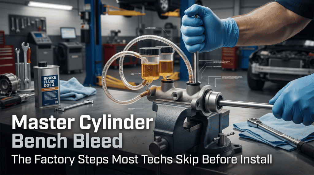
Skipping the factory master cylinder bench-bleed steps is one of the fastest ways to ruin a brand-new brake job before it even starts. Air trapped inside a fresh cylinder bore causes a spongy pedal, delayed stops, and potential brake failure under real road pressure. This is not a minor oversight.

Bench bleeding is mandatory to purge air pockets that on-car bleeding cannot reach. This factory process uses a specialized kit and specific pumping techniques to ensure a firm pedal.

This guide covers every required tool, all six precise factory steps, the critical verification checks, and the common mistakes that undo the entire process.

Master Cylinder Bench Bleed Factory Steps: Why Every Step Must Be Done Right

bench bleeding brake master cylinder with clear tubes

The master cylinder is the hydraulic pump that drives every braking action on your vehicle. When a new unit arrives from the box, the internal bore is filled with air, not fluid. These bench bleed factory steps exist specifically to remove that air before installation sends it straight into the brake lines. 

Rushing or skipping even one step means the problem follows you into the car, and no amount of on-car bleeding fully corrects air that starts inside the cylinder bore itself.

What the Bench Bleed Actually Removes from the Cylinder

Understanding the root problem makes every factory step feel intentional rather than optional. Air inside a new cylinder does not simply disappear once brake fluid is poured into the reservoir.

During actuation, the piston pushes air out of the bore and through the outlet ports. The bench bleed kit routes that displaced air back into the reservoir as visible bubbles. Without this closed recirculation loop, the air has nowhere to escape except directly into your brake lines.

  • Air compresses under pedal pressure; brake fluid does not
  • Compressed air creates pedal travel with no hydraulic force behind it
  • The factory steps ensure the bore is 100% fluid-filled before any line is connected

A properly completed bench bleed gives the hydraulic system an air-free foundation from the very first press of the pedal.

Tools to Have Ready Before Starting the Factory Steps

Having every tool prepared before starting prevents the kind of interruptions that let air back into a freshly purged cylinder. Most new master cylinders include a basic bench bleed kit in the box, but not all brands do.

Tool

Purpose

Bench bleed kit (plastic fittings and clear tubing)

Routes fluid from outlet ports back into the reservoir

Correct brake fluid (DOT 3 or DOT 4 per spec)

Fills the cylinder bore and purges air

Clear plastic tubing

Allows visual confirmation of air bubbles during actuation

Flat-tip screwdriver or wooden dowel

Activates the piston without damaging the bore

Bench vise

Holds the master cylinder level and secure throughout the process

Clean shop rags

Protects painted surfaces from brake fluid spills

Always use fresh, sealed brake fluid. An open container absorbs moisture, which, over time, degrades the cylinder’s internal seals. Cross-reference your vehicle’s exact fluid specification using a factory service manual PDF by VIN before pouring anything into the reservoir.

Step-by-Step: The Full Factory Bench Bleed Process

master cylinder secured level for bench bleeding

These are the exact factory steps used in professional shops on every master cylinder replacement. Follow the sequence in order. Rushing the piston strokes or skipping the verification check at the end causes air to re-enter and undo everything.

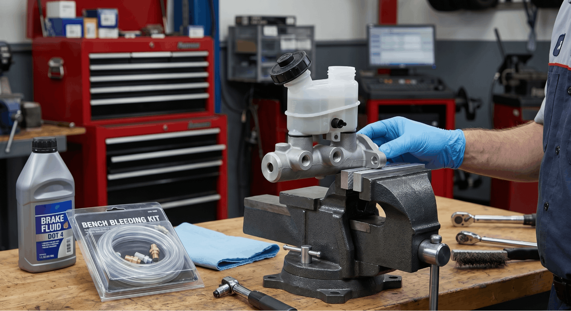
Step 1: Secure the Master Cylinder in a Bench Vise

Clamp the master cylinder by its mounting flange, never by the bore body itself. Clamping on the bore distorts the housing and ruins the unit before it is ever installed.

Keep the unit level so the reservoir sits upright throughout the entire bench bleed process. A tilted cylinder traps air in corners that are nearly impossible to purge with standard actuation.

  • Use soft jaw inserts on the vise to protect the flange
  • Confirm the reservoir cap is off and accessible before clamping
  • Check that both outlet ports are facing where you can see the tubing clearly

Step 2: Install the Bench Bleed Kit Fittings

Thread the plastic fittings from the bench bleed kit into both outlet ports by hand. Do not use tools — over-tightening plastic fittings on aluminum port threads cracks the housing.

Route the attached clear tubing up and over the side of the reservoir so both ends sit submerged below the fluid level. This closed loop is what makes bench-bleed work: it allows fluid and air to circulate back into the reservoir rather than draining onto the bench.

  • Confirm both fittings are snug with no leaking around the threads
  • Make sure the tubing loops are long enough to reach the reservoir interior
  • Keep the tubing ends fully submerged once fluid is added in the next step

Step 3: Fill the Reservoir to the MAX Line

Pour fresh, correct-spec brake fluid into the reservoir until it reaches the MAX marker. Do not overfill. Keep a clean rag under the entire unit in case of small spills during actuation.

Make sure both clear tubing ends are submerged below the fluid surface before moving forward. If the tubes sit above the fluid during actuation, air gets pulled back in with each piston release.

  • Use a clean, lint-free funnel to avoid contaminating the fluid
  • Check the reservoir spec label or your genuine OEM workshop manual for the correct DOT rating
  • Never mix DOT 3 and DOT 4 fluids inside the cylinder reservoir

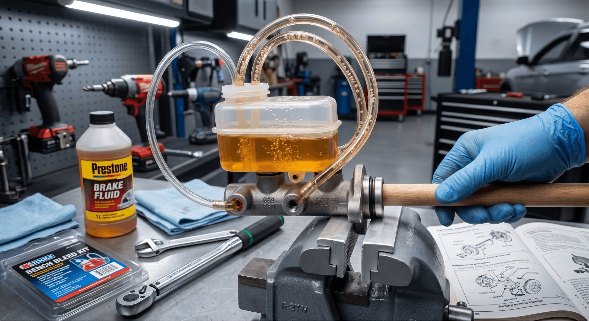
Step 4: Actuate the Piston and Watch for Air Bubbles

air bubbles visible during master cylinder bleeding

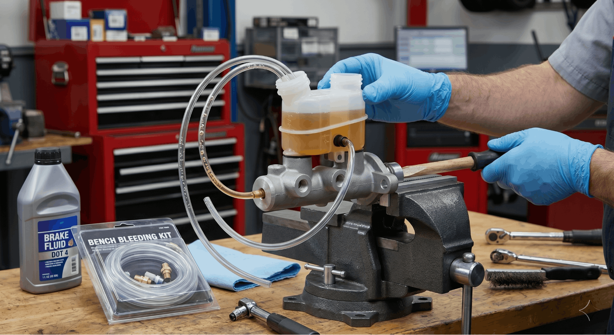
Push the piston inward slowly using your dowel or flat-tip screwdriver — about one inch of travel. Hold it depressed for two full seconds, then release slowly and steadily. Watch the clear tubing for air bubbles rising toward the reservoir.

Never snap the piston back quickly. A fast return stroke creates a vacuum inside the bore that pulls air back in through any micro-gap in the fitting seals.

  • Perform 8 to 12 slow, controlled push-and-release cycles to start
  • Top off the reservoir anytime it drops below the MIN line during cycling
  • Continue until zero bubbles appear in the tubing from both outlet ports

Both ports must show bubble-free flow simultaneously before moving to the next step. If one port still shows bubbles while the other runs clear, continue cycling until both confirm clean.

Step 5: Top Off and Cap the Reservoir Immediately

After the final actuation stroke, add fresh fluid to bring the reservoir back to the MAX line. Install the reservoir cap without any delay.

Even a few seconds of open exposure after the bleed is complete allows fresh air to enter. This is one of the most overlooked details in the entire factory steps sequence.

  • Do not set the capped unit down on a surface that could tip it
  • Keep the unit upright until the hardlines are connected during installation
  • Double-check that the cap is fully seated; a loose cap allows air entry during transport to the vehicle

Step 6: Keep the Outlet Ports Sealed Until Lines Connect

Leave the bench bleed kit fittings in the outlet ports until you are physically positioned at the vehicle with the brake hardlines in hand. Open outlet ports even for 30 seconds to reintroduce air into a freshly bled cylinder.

Transfer the unit directly from the bench to the mounting position and thread the hardlines by hand before removing any port plugs or fittings.

  • Remove one port plug at a time, only as each line is connected
  • Thread each hardline by hand before torquing to avoid cross-threading
  • Torque brake line fittings to the spec listed in your factory service documentation

Mistakes That Completely Ruin the Bench Bleed

Even a single error during these factory steps reintroduces air into the cylinder bore. Knowing what to avoid matters just as much as knowing the correct procedure.

Common Mistake

Why It Fails the Bleed

Using old, open brake fluid

Moisture contamination degrades internal seals

Letting the reservoir run dry mid-actuation

Creates a direct air path into the bore

Snapping the piston back quickly

Pulls air back in through fitting micro-gaps

Leaving outlet ports open after the bleed

Reintroduces fresh air immediately

Not confirming bubble-free flow from both ports

Declares success while air remains trapped

If the brake warning light illuminates after a completed master cylinder replacement, an incomplete bench bleed is among the first things to check. Review the brake warning light and isolate hydraulic vs. electronic faults to determine whether the fault is hydraulic or electrical before replacing additional parts.

If ABS codes follow the installation, air may have migrated into the ABS modulator. Start diagnosis with ABS warning light troubleshooting by brake system architecture before replacing any modulator components.

How to Confirm the Bench Bleed Is Fully Complete

This verification step takes 60 seconds and prevents a full reinstall if the bleed was incomplete. Do not skip it.

Push the piston inward one final time and hold it while watching both outlet port tubes. Fluid must flow clear, steady, and completely bubble-free from both ports simultaneously. Any visible air bubble at this stage means the process needs more actuation cycles.

  • Both ports must show equal and uninterrupted fluid flow
  • The reservoir level must remain stable after the cap is replaced
  • The piston must return smoothly without any spongy resistance

After the cylinder is installed and lines are connected, a full system brake bleed at all four corners is still recommended. For comparable hydraulic purge procedures on adjacent systems, power steering rack bleeding procedures cover hydraulic principles that apply directly to sealed brake circuit maintenance.

Conclusion

The master cylinder bench-bleed factory steps are not optional prep work; they are the reason a new brake system delivers a firm pedal feel from the very first stop. Air inside the cylinder bore before installation creates a problem that no on-car bleeding sequence can fully correct after the fact. 

Follow all six steps in sequence, confirm bubble-free flow from both outlet ports, and keep the reservoir capped and ports sealed until the hardlines are physically connected. One clean-bench bleed, done right on the workbench, eliminates hours of diagnostic work under the vehicle.

Frequently Asked Questions

Some manufacturers mark new units as pre-bled during production, but this label does not guarantee the bore is fully air-free when it reaches your hands.

Production handling, shipping orientation, and shelf time can all allow air to re-enter the bore through the port plugs.

It takes less than 5 minutes to run the full bench-bleed factory steps yourself and confirm bubble-free flow from both ports with your own eyes.

Trusting a box label without verification has caused numerous brake comebacks in professional shops. Always confirm the bleed status on the bench regardless of what the packaging says.

Most standard master cylinders require 8 to 15 full push-and-release cycles to purge air from both outlet ports. Larger-bore units or dual-circuit designs can require up to 20 cycles. The correct number is not fixed by counting.

it is determined entirely by when both outlet ports display completely bubble-free fluid flow through the clear tubing.

Watching the tubing is the only reliable indicator. Using a stroke count as your finish line rather than visual confirmation is one of the most common causes of an incomplete bench bleed in both DIY and professional settings.

Installing an unbled master cylinder sends trapped air directly into the primary brake hydraulic circuit.

The result is a spongy or low brake pedal that fails to build normal pressure under foot load. On-car bleeding removes air from the brake lines but cannot reliably purge air locked in the cylinder bore, since the bore is sealed once the unit is mounted.

The most reliable correction is to remove the unit from the vehicle, perform the complete bench bleed on the workbench, reinstall it, and then perform a fresh four-corner system bleed.

Attempting workarounds with the unit in place rarely produces a firm, consistent pedal.

Yes, in a meaningful way. A dual-circuit master cylinder contains two separate pistons and two independent outlet ports, each serving a different brake circuit.

Both ports must be bled individually, and both must show completely bubble-free fluid flow before the process is considered done.

The factory steps are identical for each port, but you must verify both circuits independently before capping the reservoir.

A single-circuit unit has only one bore chamber and one outlet port, which speeds up the process. Always identify your unit type and circuit configuration before starting the bench bleed to avoid missing a port.

No. Old or opened brake fluid absorbs moisture from the surrounding air over time, lowering its boiling point significantly and degrading the rubber seals inside the master cylinder.

Introducing contaminated fluid during the bench bleed means that degraded fluid goes directly into a brand-new unit on its very first use.

Always use fresh fluid from a sealed container that matches the DOT specification listed on your vehicle’s reservoir cap or in your manufacturer’s service documentation.

If you are not certain which DOT rating your vehicle requires, consult genuine OEM workshop manuals to confirm the exact specification before starting the bench bleed.

Posted on

Relay Testing Procedures & Manual Pinouts: What Most Technicians Get Wrong Every Single Time

automotive relay testing using multimeter and pinout diagram

Relay Testing Procedures and Manual Pinouts are often ignored during electrical diagnostics, and that oversight can lead to costly misdiagnoses in minutes. One incorrectly tested relay can mimic a failed fuel pump, a damaged ECU, a blown fuse, or a broken wiring harness, sending technicians in the wrong direction fast.

The safest and most accurate approach is to follow the vehicle’s manual pinout chart first, then verify relay coil resistance, terminal continuity, and switching operation with a multimeter and power source. That process removes guesswork and prevents false readings that waste time and parts.

This article explains how to identify relay terminals correctly, test relays step by step, read manual pinout diagrams, spot common failure symptoms, and avoid the testing errors that catch even experienced technicians off guard.

Relay Testing Procedures & Manual Pinouts: The Technician’s Real-World Breakdown

https://www.nxtmotors.com/wp-content/uploads/2026/05/technician-testing-automotive-relay-with-multimeter.png

Most electrical diagnosis guides skip straight to swapping the relay and see what happens. That is not a procedure; that is guessing. Real relay testing uses your workshop manual’s pinout data first, then follows a structured sequence that confirms coil health, contact operation, and voltage integrity in that exact order.

This section covers everything from reading manual pinout diagrams to running live voltage drop tests on installed relays.

Read the Manual Pinout Before Touching Anything

Before running any test, you need to know what each pin does. Skipping this step is the single most common reason technicians get wrong readings and replace good relays.

Most automotive relay pinouts follow the DIN 72552 standard. The numbers are molded directly into the relay housing. If the relay is unmarked or aftermarket, your vehicle’s service manual contains the pinout chart for the specific relay socket position.

Standard ISO Mini Relay Pin Functions:

Pin Number

Function

Circuit Type

85

Coil Ground (Negative)

Control / Low Current

86

Coil Power (Positive)

Control / Low Current

30

Common Input (Power In)

Load / High Current

87

Normally Open Output

Load / High Current

87a

Normally Closed Output

Load / High Current (5-pin only)

  • Pin 30 receives battery voltage and acts as the main power source for the switched component.
  • Pins 85 and 86 form the coil circuit, which energizes the internal electromagnet.
  • Pin 87 is the output that activates when the relay coil is energized.
  • Pin 87a is live when the relay is at rest and goes dead when energized (5-pin relays only).

Always cross-reference these numbers against your OEM workshop manual before probing. For ECU-related relay sockets, your ECU pinout charts for diagnostics are also worth checking, as some PCM-controlled relays use non-standard grounding paths through the ECU itself.

How to Identify a Bad Relay Before Any Testing

mechanic inspecting faulty relay in fuse box

Recognizing failure symptoms early saves diagnostic time. A relay does not always fail; completely intermittent faults are more common and harder to catch.

Signs your relay needs testing right now:

  • The component powered by the relay is completely dead, with no blown fuse
  • A click from the fuse box area, but the component still does not activate
  • The relay housing feels hot to the touch or has a faint burning smell
  • Fuses in the same circuit keep blowing repeatedly
  • The component works sometimes, but cuts out randomly under heat or vibration

A clicking relay that still fails to activate the circuit points specifically to burned or pitted contact points inside. The coil is working, the switch is not. That distinction matters because it changes the entire testing procedure you run next.

Step-by-Step Relay Testing Procedure Using a Multimeter

This is the full bench test. Remove the relay from the socket first. Testing it in-circuit introduces parallel paths that corrupt your readings.

Tools required:

  • Digital multimeter (DMM) with resistance and continuity modes
  • 12V battery or bench power supply
  • Two jumper wires with alligator clips
  • Vehicle workshop manual with relay pinout diagrams

For accurate sensor-based multimeter work across other circuits, multimeter sensor testing via workshop manuals covers the exact settings and probe techniques that apply to relay sockets as well.

Step 1 Coil Resistance Test

Set your multimeter to ohms (Ω). Place the probes on pins 85 and 86. A healthy 12V automotive relay reads between 50 and 120 ohms. Any reading outside this range means the coil is compromised.

  • OL or infinite resistance = open coil, the relay cannot energize, replace it
  • Near 0 ohms = shorted coil, will blow fuses repeatedly, replace it

Step 2 Contact Continuity Test (Relay Unpowered)

Switch your multimeter to continuity mode. With the relay at rest:

  • Probe pins 30 and 87; you should get NO continuity (no beep). This is the normally open circuit.
  • Probe pins 30 and 87a (5-pin relays). You SHOULD get continuity (an audible beep). This is the normally closed circuit.

If you get continuity between 30 and 87 at rest, the contacts are welded shut. That relay is stuck closed and must be replaced.

Step 3: Energize the Coil and Test Live Contacts

Connect one jumper wire from the positive terminal of your 12V battery to pin 86. Connect the second jumper from the battery negative to pin 85. You should hear a sharp, firm click immediately. A weak click or buzzing sound indicates internal mechanical failure.

With power held on:

  • Probe pins 30 and 87 continuity should now be present (beep confirmed)
  • Probe pins 30 and 87a (5-pin) continuity should now be gone (beep stops)

If the relay clicks but the contacts do not switch, the contacts are defective. Replace the relay.

Step 4 Voltage Drop Test (In-Circuit, Under Load)

This test catches relays that pass bench testing but fail under real operating conditions, particularly cooling-fan and fuel-pump relays.

Set your multimeter to DC volts. Probe pins 30 and 87 while the circuit is active and the component is running. A healthy relay shows less than 0.1V drop across the contacts. A reading of 0.3V or higher means the contacts are worn, corroded, or partially burned. Heat builds up quickly at this resistance level, leading to intermittent failures.

Reading Relay Pinout Diagrams From a Workshop Manual

technician checking relay pinout at fuse box

Factory service manuals include two critical resources for relay diagnosis: the fuse/relay box diagram and the individual relay circuit schematic.

How to use your manual pinout correctly:

  • Open the fuse box lid. Most vehicles print a simplified relay location diagram there
  • Cross-reference with the full electrical section of the workshop manual to find the relay’s circuit schematic
  • The schematic shows what controls pin 86 (the trigger source) and what load connects to pin 87
  • Identifying the trigger source tells you whether the relay is controlled by the ECU, a body control module, or a simple switch

If the relay socket itself is suspect, loose terminals, corrosion, or burned plastic, this connects directly to hidden chassis ground points via manual, since a bad ground at the relay socket produces the same symptoms as a failed relay coil.

Relay socket voltage checks (in-circuit, ignition on):

Terminal

Expected Reading

What It Confirms

Pin 86

12V (switched or constant)

Trigger signal present

Pin 85

0V (solid ground)

Ground path intact

Pin 30

12V (battery)

Power supply intact

Pin 87

0V at rest / 12V when triggered

Relay output working

If pin 30 shows no voltage, the power feed to the relay is open. That is a wiring or fuse problem, not a relay fault. If pin 85 does not ground, you have a ground circuit issue. A failed ground here mimics a dead relay completely. Wiring diagrams to trace shorts explain how to follow these paths back to the fault using OEM schematics.

Common Relay Failure Types and What the Test Results Mean

Understanding the failure mode helps you go beyond simply replacing the part and actually fixing the root cause.

Failure Type Comparison Table:

Failure Mode

Coil Resistance

Contact Continuity

Symptoms

Open coil

OL / infinite

Normal at rest

No click, dead component

Shorted coil

Near 0 ohms

Normal at rest

Blown fuses, no click

Welded contacts (closed)

Normal

Continuity at rest (NO pins)

Component stays on constantly

Burned contacts

Normal

No continuity when energized

Clicks, but the component stays dead

Intermittent contact

Normal cold

Fails when warm

Works, then cuts out

Welded contacts after a motor circuit often indicate the motor seized or shorted, drawing too much current through the relay. Replacing only the relay without addressing the overload causes the new relay to fail the same way. Check for parasitic drains from factory schematics if the relay was protecting a circuit with suspected current overconsumption.

Conclusion

Relay testing procedures are only as reliable as the manual pinout data you start with. Guessing pin functions and skipping the coil resistance test lead to replaced parts that didn’t need replacing and to missed faults that do.

Start with your workshop manual, confirm the pin layout against DIN 72552, run the coil resistance test, check both contact states, and verify in-circuit voltage if the bench test passes. That sequence catches every common relay failure mode: open coils, shorted coils, burned contacts, and welded switches.

A relay costs less than $20. A missed fault costs hours. The procedures in this guide give you the diagnostic confidence to tell the difference every time.

Frequently Asked Questions

Yes, and this is more common than most technicians expect. A relay can pass all bench tests when cold, but fail under heat once installed and in operation.

Intermittent contact failure due to thermal expansion is the main cause. The most reliable method for catching this is the in-circuit voltage drop test run with the component under load.

A voltage drop of 0.3V or more across pins 30 and 87 during operation confirms failing contacts, even when the relay clicks normally.

Always test warm if the symptom only appears after the vehicle has been running for some time.

A clicking relay indicates that the coil is energized and the internal armature is moving. However, the contacts inside may be burned, pitted, or corroded enough that they no longer make proper electrical contact even when they physically close.

Run a continuity test across pins 30 and 87 with the relay powered. If there is no continuity despite the click, the contacts are the problem.

This is a very specific failure mode that requires replacing the relay. Do not assume a clicking relay is a good relay without confirming continuity under power.

The simplest method is the swap test. Pull the suspected relay and replace it with an identical relay from another circuit in the same fuse box, using the same part number and pin configuration.

If the fault moves to a component in the borrowed circuit, the original relay is confirmed bad. You can also use a 12V test light connected across pins 30 and 87 while energizing the coil with jumper wires.

If the test light illuminates when you apply power to pins 85 and 86, the contacts are closing properly. Neither method replaces a proper multimeter test, but both give fast confirmation in a pinch.

The numbering comes from the DIN 72552 automotive terminal standard, which assigns function-based numbers rather than sequential ones.

These numbers were established across the entire electrical system, not just for relays. For example, terminal 30 means the battery-positive terminal is directly connected to all components, including relays, switches, and fuses.

Terminal 15 means ignition-switched power. Terminals 85 and 86 specifically identify relay coil connections across the standard.

This system allows any trained technician to read any relay pinout in any vehicle without needing a component-specific key, as long as the relay follows the ISO mini format.

The core procedure is the same, but a 5-pin relay adds one extra check. The fifth pin is 87a, which is the normally closed contact. At rest with the relay unpowered, you should have continuity between pins 30 and 87a. When you energize the coil, that continuity disappears as the switch transfers to pin 87. Testing a 5-pin relay requires confirming both states of both contact sets:

The normally open circuit is between 30 and 87, and the normally closed circuit is between 30 and 87a. Missing the 87a check means you could pass a relay that has a broken normally-closed contact, which matters for circuits that rely on that closed state during normal operation.

Posted on

Safely Depressurize Systems for Fuel Pumps: What Most Guides Won’t Tell You

Mechanic safely removing fuel pump relay in engine bay to depressurize fuel system during repair

Knowing how to safely depressurize fuel pump systems is not just a best practice. It is the difference between a clean repair job and a dangerous spray of pressurized fuel that can ignite in seconds. Most modern fuel systems hold between 40 and 450 PSI, depending on the engine type, and that pressure does not vanish the moment you turn the key off.

To safely depressurize, remove the fuel pump fuse or relay, start the engine, and let it stall to bleed residual pressure. Verify by checking the fuel rail for pressure. Always work in a well-ventilated space, wear safety glasses, and keep a fire extinguisher nearby.

This guide covers three proven depressurization methods, step-by-step safety prep, fuel system pressure ranges by engine type, common mistakes to avoid, and what to do after the job is done.

Safely Depressurize Systems for Fuel Pumps: The Steps That Actually Work

technician safely relieving fuel system pressure before repair

Too many DIY repairs go wrong right here. People skip the pressure relief step, crack open a fuel line, and suddenly get a face full of pressurized gasoline. This section covers every method used by actual technicians, from the standard fuse-pull method to Schrader-valve release and scan-tool depressurization on GDI engines.

Fuel System Pressure Ranges You Should Know First

Before touching anything, understand what you’re working with. Not all fuel systems maintain the same pressure, and the method for safely depressurizing varies by engine type.

Engine Type

Typical Fuel Rail Pressure

Carbureted

4 to 7 PSI

Port Injection (MPFI)

35 to 65 PSI

Gasoline Direct Injection (GDI)

200 to 2,900 PSI

Diesel Common Rail

10,000 to 30,000 PSI

GDI systems are the most hazardous to work on without proper depressurization. A scan tool command or factory service procedure is required for these, not just a fuse pull.

If you need model-specific pressure specs, check the correct factory service manual PDF by VIN for the exact value for your vehicle.

Safety Gear and Workspace Setup Before You Start

technician preparing safety gear before fuel repair

A lot of people skip prep and head straight to the fuse box. That approach tends to end badly. Spend five minutes here, and the rest of the job goes smoothly.

  • Work in a well-ventilated area or open garage. Fuel vapors are heavier than air and collect at floor level.
  • Wear nitrile gloves and safety goggles. Latex gloves absorb fuel and cause skin irritation over time.
  • Disconnect the negative battery terminal before disconnecting any fuel line.
  • Keep a fire extinguisher nearby. A Class B extinguisher handles fuel fires.
  • Place absorbent shop rags under any connection you plan to open.
  • Never smoke or allow open flame near the work area.

These steps apply regardless of which depressurization method you use. Skipping safety gear is how minor jobs turn into emergency room visits.

Method 1: Fuel Pump Fuse or Relay Removal (Most Common)

This is the method most workshop manuals recommend for standard port injection and multi-point fuel systems. It works on the vast majority of vehicles built after 1990.

Step 1: Open the fuse/relay box. Location varies, but it is usually under the hood, near the battery, or inside the cabin, under the dashboard. Check your owner’s manual or a genuine OEM workshop manual for the exact fuse location.

Step 2: Locate the fuel pump fuse or relay. It is usually labeled FP, FUEL PUMP, or similar.

Step 3: With the engine off, pull the fuse or relay out completely.

Step 4: Attempt to start the engine. It will crank, stumble, and stall as residual fuel burns off. Let it crank for about 10 seconds.

Step 5: Try starting it once more. If it won’t fire at all, the system is depressurized.

Step 6: Turn the ignition to OFF. Now disconnect the negative battery cable.

Important note: Some vehicles store a Diagnostic Trouble Code (DTC) when the fuel pump relay is removed while cranking. Use a scan tool to clear it after the repair. You can learn how to read OBD-II codes using manual flowcharts if you need to clear those codes yourself.

Method 2: Schrader Valve Release on the Fuel Rail

releasing fuel pressure at rail valve

Some vehicles have a Schrader valve on the fuel rail, similar to a tire valve stem. This is often the fastest method when the engine cannot run.

Step 1: Locate the fuel rail on the engine. The Schrader valve is a small metal port, usually capped.

Step 2: Place a rag firmly around the valve to catch fuel spray.

Step 3: Using a small flathead screwdriver, press the valve’s center pin inward.

Step 4: Hold the rag tight. Fuel will spurt out briefly, then slow to a drip. That means pressure has been released.

Step 5: Dispose of the fuel-soaked rag properly. Do not leave it near any heat source.

This method works well for port injection systems but does not fully depressurize a GDI high-pressure fuel system. For those, you still need a scan tool or factory procedure.

Method 3: Scan Tool Depressurization for GDI Systems

Gasoline direct injection engines run at pressures up to 2,900 PSI. A fuse pull alone is not sufficient for these fuel systems. The correct approach is to use a scan tool with bidirectional control capability.

Step 1: Connect a compatible scan tool to the OBD-II port.

Step 2: Navigate to the fuel system or engine control menu. Look for a “depressurize fuel system” function.

Step 3: Enable the command. The engine will run rough as the high-pressure fuel pump is starved, then stall when the pressure nears zero.

Step 4: Monitor the fuel rail pressure sensor PID on the scan tool. Confirm pressure has dropped to near 0 PSI before proceeding.

Step 5: Turn the key off, then disconnect the battery.

For GDI vehicles, always reference the factory procedure. If you use multimeter sensor testing via workshop manuals as part of your diagnosis, those steps also apply when verifying the fuel rail pressure sensor is reading correctly after the repair.

After Depressurization: What to Do Next

The system is now depressurized, but the job is not done yet. Here is what matters before you start pulling components.

  • Double-check for residual pressure by pressing a rag against the Schrader valve or slightly loosening a fitting. If fuel sprays, pressure remains.
  • Inspect all fuel lines for cracks or brittleness before disconnecting them.
  • Never use sparking tools near open fuel lines. Non-sparking tools are the correct choice here.
  • After the repair, reprime the system by cycling the ignition key to ON (not start) two to three times, waiting 3 to 5 seconds each time before cranking.
  • Check for leaks visually and by smell before fully starting the engine.

One thing many guides skip: after reinstalling a fuel pump, always replace the O-ring or gasket at the tank opening. The old seal has likely hardened and will leak under pressure.

Conclusion

Depressurizing a fuel system before working on a fuel pump is not optional. It is the step that separates a safe repair from a dangerous one.

The relay method handles most standard systems; the Schrader valve works when the engine won’t run; and GDI vehicles require scan tool procedures because the raw pressure is too high to release manually. 

Know which method applies to your vehicle, wear the right gear, and always verify pressure is gone before disconnecting anything. The repair itself is often straightforward once the system is safe to open.

Frequently Asked Questions

Yes, and this comes up more often than people expect. If the engine won’t crank, pull the fuel pump relay or fuse first. Then attempt to start the vehicle, even if it won’t fire. The cranking action still cycles residual fuel through the injectors and bleeds off line pressure.

If the vehicle has a Schrader valve on the fuel rail, you can press the center pin with a flathead screwdriver while wrapping a rag tightly around the valve. That releases most of the rail pressure directly without needing the engine to run.

For GDI systems where the engine is completely dead, connecting a scan tool and using a bi-directional depressurization command is the most reliable path. Always disconnect the battery after, regardless of which method you use.

It depends on the vehicle and the condition of the fuel pressure regulator. In most healthy port injection systems, some residual pressure remains in the fuel rail for 30 minutes to several hours after shutdown.

A failing check valve inside the fuel pump can allow pressure to bleed back to the tank much faster, sometimes within minutes. GDI systems typically see faster high-pressure-side dissipation than low-pressure-side dissipation.

Never assume pressure is gone just because the car has been sitting overnight, especially on vehicles with a known history of holding rail pressure well. Always verify fuel rail pressure using a Schrader valve test or a scan tool before opening any connections.

Technically possible on a carbureted engine where pressure is only 4 to 7 PSI. For any fuel-injected vehicle, it is not safe. Port injection systems hold 35 to 65 PSI, and disconnecting a fuel line without depressurizing first will cause a spray of pressurized gasoline that can cover skin, eyes, and the surrounding engine bay.

That creates a serious fire risk, especially near hot surfaces or ignition sources. GDI systems at 2,900 PSI can cause injection-type injuries where fuel penetrates the skin directly. These injuries look minor but are medical emergencies. The short time it takes to properly depressurize is never worth skipping.

The engine may crank and fail to start on the first few attempts, or start briefly and stall. This is because air has entered the fuel lines, and the new pump needs several seconds to fill the lines and build operating pressure.

Cycling the ignition key to the ON position three times, waiting about five seconds each time before cranking, primes the system and pushes air out. On some vehicles, especially diesel engines, air in the fuel system can cause extended cranking or rough running even after the initial startup.

If the vehicle struggles to start after multiple key cycles, check for kinked lines, improper connections, or a faulty new pump before assuming a larger issue.

Yes. A fuel pressure regulator that sticks in the closed position can trap pressure in the fuel rail even after the pump is disabled.

In those cases, the fuse-pull method may not fully bleed the system because pressure cannot return to the tank through the regulator return line. You would still see elevated rail pressure when testing the Schrader valve.

The fix is to confirm regulator function before the repair, or use the Schrader valve method directly to manually release rail pressure regardless of regulator condition.

If you are diagnosing a suspected regulator issue alongside a fuel pump replacement, a free online repair manual is a starting point, though it is always worth knowing whether free online car repair manuals are safe to use before relying on one for technical procedures.

Posted on

Power Steering Rack Bleeding Procedures: The Step Most Drivers Skip

Mechanic performing power steering bleeding process with fluid reservoir and steering wheel cycle in workshop

Failing to follow proper power steering rack bleeding procedures is how a simple repair turns into a full rack replacement. Trapped air inside the steering rack causes whining, stiff response, and unpredictable handling that compounds over time.

Effective repair requires vacuum-assisted bleeding and lock-to-lock cycling to purge air pockets. This involves raising the front wheels, filling the reservoir, and cycling the wheel 20-50 times, engine-off, then engine-on, until the bubbles disappear.

This article covers the exact steps, the right tools, and the most common mistakes that can cause the job to fail.

Power Steering Rack Bleeding Procedures: Why Most Attempts Fall Short

technician bleeding power steering system while turning steering wheel in workshop

Most drivers top off the fluid reservoir and assume the job is done. But bleeding a power steering rack correctly demands a specific sequence of steps. Air pockets hide deep inside the rack housing, the pump inlet, and the return lines.

Without the right method, the system keeps pulling air back in, and symptoms return within days. This section breaks down every step with precision.

Why Air Gets Into the Rack in the First Place

technician inspecting cracked power steering hose and rack system for air leak points

Understanding where air enters helps you prevent it from reentering. Air can intrude during hose replacement, rack removal, pump swaps, or after running the reservoir dry.

Once inside, the air compresses and expands with every steering input. That inconsistency causes groaning, hard spots, and delayed response, mimicking a failing rack. The air circulates through the entire hydraulic circuit; a surface-level fluid top-off makes no difference.

Common causes of air intrusion:

  • Running the reservoir empty during a repair
  • Loose or improperly seated return line fittings
  • Cracked or aged power steering hoses
  • Improper rack installation without pre-filling the circuit
  • Overfilling and then releasing pressure without cycling

Tools Required Before Starting the Bleeding Process

Having the right tools up front prevents mid-job stops. You need a vacuum bleed kit, a fluid transfer pump, fresh power steering fluid that meets OEM specifications, and a set of clean rags. A floor jack and jack stands are required; bleeding with the wheels on the ground adds resistance and hides incomplete results.

Tool

Purpose

Vacuum bleed pump

Pull air from the reservoir under negative pressure

Fluid transfer pump

Extract old or aerated fluid cleanly

OEM-spec PS fluid

Refill without introducing incompatible additives

Floor jack and stands

Raise front wheels for unloaded lock-to-lock cycling

Shop rags and a funnel

Keep the work area clean and prevent contamination

Fluid type matters more than most people expect. Check your factory service manual PDF by VIN to confirm which spec applies to your vehicle before opening the reservoir.

The Exact Bleeding Procedure: Step by Step

technician checking power steering fluid with car front wheels lifted on jack stands

This is where most DIY bleeds fail; the sequence matters more than the effort. Follow these steps in order and do not skip ahead.

Step 1: Raise the front wheels off the ground

Jack up the front of the vehicle so both tires are completely free. This removes road resistance, allowing you to cycle the steering lock to lock without fighting the car’s weight. Bleeding with the wheels on the ground produces unreliable results every time.

Step 2: Check and fill the reservoir

Pull the reservoir cap and check the fluid level. Top off the MAX line using the correct power steering fluid for your vehicle. Refer to a genuine OEM workshop manual if you are unsure which fluid type is required. Never mix fluid types; this causes internal foaming that mimics trapped air.

Step 3: Apply a vacuum to the reservoir

Attach the vacuum bleed pump to the reservoir opening. Pull the vacuum and hold it for 30 to 60 seconds. You will see bubbles rising through the fluid. That is air escaping the system. Release, let the fluid settle, then top off again before the next cycle.

Step 4: Cycle the steering lock to lock with the engine off

Turn the wheel slowly from full left lock to full right lock. Do this 10 to 15 complete cycles. This pushes fluid through the rack and forces trapped air pockets toward the reservoir where they can escape. Do not start the engine yet; manual cycling first clears the bulk of the air.

Step 5: Repeat vacuum and refill

Apply vacuum again after cycling. More bubbles will appear. Repeat the fill-vacuum-cycle sequence until no more bubbles rise during the vacuum hold. This may take two or three rounds, depending on how much air entered the system during the repair.

Step 6: Start the engine and cycle again

Start the engine and let it idle. Turn the wheel lock to lock slowly 3 to 5 full cycles. Watch the reservoir carefully. Foaming or a sharp drop in fluid level indicates air is still present. Top off and repeat. Never hold the wheel at full lock for more than 2 to 3 seconds with the engine running, or you risk overloading the pump seals.

Step 7: Final level check and road test

Shut off the engine. Check the fluid level one final time. It should be at or near the MAX line with no foaming or cloudiness visible. Take the vehicle for a short drive and feel for smooth, consistent steering response across the full range. Any remaining whine or stiffness means another bleeding cycle is needed.

Mistakes That Undo the Entire Bleed

technician observing foamy power steering fluid during bleeding process with car on jack stands

Even with the right tools, small errors ruin the result. The most common is starting the engine too early, before manual cycling clears most of the air. Another frequent mistake is using an incompatible fluid type, which can foam internally and produce symptoms identical to those of trapped air.

Avoid these errors:

  • Holding lock-to-lock position with the engine running for more than 2 to 3 seconds
  • Skipping the vacuum step and relying on cycling alone
  • Mixing fluid types or using a universal substitute without verifying compatibility
  • Bleeding with the car on the ground, road resistance masks incomplete results
  • Forgetting to re-check the fluid level between each cycle

If your vehicle has also been showing car shaking while driving, along with steering symptoms, that combination sometimes points to a deeper suspension or alignment issue rather than air in the rack alone.

How to Confirm the Rack Is Fully Bled

A properly bled power steering rack feels smooth across the entire steering range. No dead spots. No whine at idle. No groaning during slow-speed turns or parking lot maneuvers.

Signs a successful bleed looks like:

Indicator

Expected Result

Pump noise at idle

Silent or near-silent

Steering effort

Consistent across the full lock-to-lock range

Fluid level after a 10-minute drive

Stable, no drop

Fluid appearance in the reservoir

Clear, not cloudy or foamy

Return line feel

No vibration or shudder at low speeds

If symptoms return after a few days, inspect the return line fittings and rack seals for internal leaks. Air re-entering the system after a completed bleed almost always means a seal is failing, not a procedure error. That pattern also ties into similar principles used in coolant bleeding procedures, where a returning air pocket indicates a leak rather than an incomplete bleed.

Conclusion

Bleeding a power steering rack is not complicated, but it demands patience and the correct sequence. Most failed attempts come from skipping the vacuum step or rushing to start the engine before the manual cycles are finished.

Follow the steps in order, confirm the correct fluid spec, and the system will respond as it should. If symptoms persist after two full bleeding cycles, the rack or pump likely needs professional inspection. Continuing to drive on a compromised system accelerates internal wear fast.

Frequently Asked Questions

A proper bleed typically takes 30 to 45 minutes when done correctly. This includes multiple vacuum pulls, lock-to-lock cycling with the engine off, and repeating those steps with the engine running. Rushing is the main reason symptoms return.

If the system had a major air intrusion, such as after a full rack replacement, budget closer to an hour to make sure all trapped air is fully purged before driving. 

Systems that were run dry require extra attention during the initial vacuum hold cycles.

Yes, but it takes longer and produces less reliable results. Without a vacuum pump, you rely entirely on lock-to-lock cycling to move air out.

The process still works, but requires more cycles, often 20 to 30 turns with the engine off before switching to engine-on cycling. The vacuum method is faster and more thorough because it actively draws air out rather than just circulating it.

For a rack that was fully removed and reinstalled, using a vacuum pump is strongly recommended over cycling alone.

Persistent whining after a full bleed usually points to one of three things: air still trapped deep in the rack, a pump cavitating due to a restricted inlet hose, or internal rack wear creating low-pressure zones.

Check the return line and inlet hose for kinks or soft sections first. Also, confirm the fluid level has not dropped; a slow internal leak can reduce the level enough to reintroduce air within a short drive, making it appear as though the bleed failed.

Yes, always. Whenever the power steering rack is removed, the hydraulic circuit is opened, allowing air to enter the lines and fittings.

Even a rack bench-tested before installation will have air in its connection points. Skipping the bleed after a rack replacement risks cavitating a brand-new pump because it runs partially dry or against air pressure during the first drive before fluid fully circulates through the system. This kind of damage is not covered under most warranties.

Always use the fluid specified in your vehicle’s owner manual or a verified OEM source. Many modern vehicles require a specific ATF type or dedicated power steering fluid mixing types, which causes foaming that mimics trapped air and makes diagnosis harder.

Universal fluids work in older systems, but using them in newer racks with synthetic seals can degrade those seals and cause leaks over time. Matching the correct fluid spec before starting the bleed is just as important as the procedure itself.

Posted on

Suspension Bushing Pre-Load Instructions: The Step Most Mechanics Skip That Destroys Your Ride

Mechanic tightening suspension bushing bolts at ride height using torque wrench in workshop

Skipping proper suspension bushing pre-load instructions is one of the fastest ways to ruin a fresh install. Most DIYers torque everything down with the suspension hanging and wonder why the car rides rough or makes noise within weeks.

To fix this, torque rubber bushing fasteners only when the vehicle is at normal ride height. This prevents rubber pre-twisting, avoids tearing, and ensures proper handling.

This guide covers what pre-load actually means, why it matters, which bushings need it, and the exact step-by-step process to get it right the first time.

Suspension Bushing Pre-Load Instructions: Why Getting This Wrong Costs You Twice

technician torquing crankshaft pulley during engine reassembly after timing belt service

Every suspension component connected by a rubber bushing relies on correct rotational positioning at rest. Lock those bushings at the wrong angle, and the rubber spends every mile fighting to untwist itself. Follow these pre-load instructions, and the bushings settle exactly where they were designed to live.

Getting this right is not just about longevity. It directly affects ride height, handling balance, and noise. A surprising number of post-install complaints, from clunking to uneven corner height, trace back entirely to skipped pre-load steps.

What Bushing Pre-Load Actually Means

Before jumping into the steps, it helps to understand what is actually happening inside the bushing. Rubber bushings bond an inner steel sleeve to an outer steel shell through a rubber fill. They do not rotate freely like a bearing. Instead, they flex within their rubber core.

When you remove a control arm and reinstall it with the suspension hanging at full droop, the arm sits at a steep downward angle. Tightening the mounting bolt at that angle locks the inner sleeve in a position that is far from where it will actually live when the car is on the ground.

Once the car returns to ride height, the rubber has to twist to reach its normal position. But it cannot, because the bolt is already clamped tight. That constant twist is called false pre-load. It creates:

  • Accelerated bushing wear from continuous rotational stress
  • Ride harshness because the rubber is already partially deflected before any bump loads arrive
  • Uneven ride height when the twist is different from corner to corner
  • Clunking or creaking noises are often misdiagnosed as bad shocks or loose hardware
  • Premature bushing cracking, especially in colder climates

Which Suspension Bushings Require Pre-Load

technician torquing suspension control arm bushing at ride height on lift

Not every bushing in the car needs this treatment. Knowing which ones matter saves time and prevents overthinking.

These bushings always require pre-load torquing:

  • Lower control arm inner pivot bushings (the most common failure point when skipped)
  • Upper control arm inner pivot bushings
  • Rear trailing arm bushings
  • Rear toe, arm, and camber arm bushings on multi-link setups
  • Panhard rod / lateral link bushings
  • Sway bar end link bushings (snug at ride height before final torque)
  • Subframe mounting bushings on reassembled subframes

These generally do not require pre-load:

  • Ball joints (they use a spherical pivot, not a bonded rubber bushing)
  • Sway bar clamp bushings (they are not pivot points)
  • Strut top mounts (load is applied axially, not rotationally)

If a bushing is a pivot point and uses bonded rubber to control the range of motion, assume it needs pre-load.

Tools You Need Before Starting

technician preparing suspension preload tools with car on jack stands in workshop

Getting pre-load right does not require a 4-post lift, though having one helps significantly. Gather the right tools first, and the process becomes straightforward.

Required tools and equipment:

  • Floor jack (minimum 2-ton rating)
  • Jack stands (rated for your vehicle’s weight)
  • Torque wrench rated for your factory spec range
  • Vehicle ramps (a low-cost alternative to a 4-post lift)
  • OEM factory service manual or trusted torque spec source

For torque specifications specific to your wheel bearing hardware and related fasteners during this process, reviewing wheel bearing hub torque specifications ensures nothing nearby gets over- or under-tightened during reassembly.

Step-by-Step Pre-Load Instructions for Rubber Bushings

Follow each step in order. Skipping even one defeats the purpose of the entire process.

Step 1: Record Your Ride Height Before Disassembly

Measure the distance from the center of the wheel hub to the bottom edge of the fender arch. Do this at each corner and write it down. This measurement becomes your reference when simulating ride height on the jack.

Step 2: Install All Suspension Components Hand-Tight Only

Reinstall all arms, links, and related hardware. Thread every bushing bolt or nut by hand until snug. Do not torque anything to spec yet. The components need to be free to find their natural position once loaded.

Step 3: Load the Suspension to Ride Height

technician setting suspension to ride height using jack and measuring hub height in workshop

This is the critical step. You have several options depending on your setup:

  • Option A (Best): Drive the car forward off the jack stands onto the ramps. The suspension sits near ride height, and the underside remains accessible.
  • Option B: Use a floor jack under the lower control arm or hub. Raise the suspension until the car body just begins to lift off the jack stands. At that point, the suspension is loaded at approximately normal ride height.
  • Option C: Lower the car fully to the ground and use the undercar access you have. Best for vehicles with enough clearance.

When using Option B, use your pre-disassembly hub-to-fender measurement to confirm you have reached the correct height before torquing.

Step 4: Fully Loosen and Re-Snug Each Bushing Bolt

This step surprises most people, but it matters. Even with the suspension loaded, a bolt hand-tightened while the arm was at droop can leave the bushing slightly twisted. Loosen each bushing bolt fully, let the arm settle naturally under load, then re-snug the bolt. Now the inner sleeve is sitting exactly where it wants to be.

Step 5: Torque to Factory Specification

technician torquing suspension control arm bolts at ride height using torque wrench

With the suspension loaded and each bolt freshly snugged, torque every bushing fastener to the manufacturer’s specification. Work methodically from inner pivots outward. Do not bounce or jounce the suspension between bolts. Keep the load steady throughout.

If you are unsure how to locate your vehicle-specific torque values, a factory service manual PDF by VIN gives you the exact figures from the OEM documentation.

Step 6: Lower the Vehicle and Bounce It

Once torqued, lower the car fully to the ground. Push down firmly on each corner three to four times to settle the suspension. This helps confirm the bushings have seated correctly and that nothing shifts post-torque.

Check for any audible creaks or resistance. A properly pre-loaded rubber bushing should be silent and compliant.

Pre-Load Methods Compared

Method

Ease of Access

Accuracy

Best For

4-post lift

Excellent

High

Shop environments

Vehicle ramps

Good

Good

Home garage

Floor jack under the hub

Moderate

Good

DIY single-corner work

Lower to the ground fully

Limited undercar access

Highest

Low-slung vehicles

The ramp method remains the most practical option for home mechanics performing full-suspension rebuilds. Before you start, review safe jacking and lifting points in your manual to prevent vehicle damage and keep the process safe.

What Happens If You Skip Pre-Load

Skipping pre-load does not always result in immediate failure. That is actually what makes it dangerous. The damage accumulates silently over thousands of miles before becoming obvious.

Short-term consequences (0 to 10,000 miles):

  • Uneven ride height side to side
  • Subtle handling imbalance, especially on turn-in
  • Occasional creak or pop from affected corners

Long-term consequences (10,000 miles and beyond):

  • Cracked or torn rubber bushing material
  • Inner sleeve walking or rotating inside the bushing shell
  • Accelerated wear to adjacent components, including ball joints and tie rods
  • Full bushing failure requiring complete arm replacement

Shops that see repeat bushing failures within 30,000 miles on vehicles like the Cadillac SRX or multi-link European platforms almost always trace it to exactly this missed step.

Polyurethane vs. Rubber Bushings: Pre-Load Differences

technician comparing rubber and polyurethane suspension bushings during installation process

The pre-load rules above apply specifically to bonded rubber bushings. Polyurethane bushings operate differently, and it is worth understanding the distinction.

Rubber bushings: The rubber is bonded (chemically adhered) to both inner and outer sleeves. Movement happens entirely through rubber deflection. These must be torqued at ride height.

Polyurethane bushings: The bushing floats between the sleeves and is held by a lubricant film. The inner sleeve can rotate within the bushing body. These are less sensitive to torque angle because the sleeve is not bonded to the rubber.

That said, polyurethane aftermarket bushings still benefit from being torqued at or near ride height. The main difference is that the consequences of not doing so are less severe compared to bonded rubber.

If you are sourcing technical specifications for any of this work, genuine OEM workshop manuals provide the most accurate bushing torque values and installation notes directly from the manufacturer.

Pre-Load Checklist Before Final Sign-Off

Use this before lowering the vehicle for the last time:

  • All bushing bolts loosened and re-snugged after loading
  • Suspension at measured ride height confirmed before torquing
  • Every fastener is torqued to factory spec with a calibrated torque wrench
  • Vehicle bounced on all four corners post-torque
  • No audible creak or resistance when manually pressing each corner
  • Wheel alignment scheduled (always required after any suspension work)

A proper wheel alignment is non-negotiable after any suspension rebuild. Even correctly pre-loaded bushings will not compensate for an alignment that is now out of spec from new component installation.

Conclusion

Suspension bushing pre-load is not an optional refinement. It is a fundamental mechanical requirement built into how rubber bushings actually function.

The instructions in this guide reflect one core principle: rubber bushings must be locked in their neutral, loaded position at ride height, not in the drooped position the suspension sits in while on a lift.

Follow the six steps above, use your ride height measurement as a reference, and your bushings will perform exactly as designed throughout the component’s life. Skip it, and even the best quality parts will fail ahead of schedule.

Frequently Asked Questions

Yes, jacking under the lower control arm or hub is a valid method. Raise the corner until the car body just begins to lift off the jack stands.

At that point, the suspension is close to its normal ride height, and the bushing’s inner sleeve is roughly in its neutral rotational position. It is not as accurate as driving onto ramps because the weight distribution is slightly different, but it works reliably for single-corner work.

Use your pre-disassembly hub-to-fender measurement to confirm the suspension is at the right height before applying final torque. This method is widely used by professional technicians working on individual corners.

Sway bar end link bushings benefit from being snugged at ride height before final torquing, though the consequences of skipping are less severe compared to control arm inner pivots.

The end link sits at a slightly different angle when the suspension is drooped versus loaded, and torquing it at droop can place a slight pre-twist into the rubber. For sway bar clamp bushings that bolt to the chassis, preload is not required because they compress axially rather than rotate.

The rule of thumb: if the bushing is part of a pivot point that changes angle with suspension travel, torque it when it is loaded.

Uneven ride height after a suspension rebuild is one of the most common signs that bushings were torqued at full droop rather than at ride height.

When the bushing’s inner sleeve is locked in the wrong rotational position, the rubber exerts a restoring force as it tries to return to its neutral state. This can effectively lift one corner slightly.

The twist is rarely perfectly equal on both sides, which produces an uneven stance. 

The fix is to loosen the relevant bushing bolts, load the suspension to ride height, re-snug, and re-torque. A wheel alignment is still required afterward.

Yes, subframe bushings are often overlooked, but they follow the same principle. When a subframe is reinstalled with the vehicle on a lift, the mounting bushings are torqued with no vehicle weight pressing down through them.

Once the car is back on the ground, the subframe settles slightly, and the bushings shift. 

For most OEM subframe designs, the best practice is to snug the subframe mounting bolts, lower the vehicle fully to the ground, bounce it a few times, and then final-torque the mounting bolts. 

This ensures the subframe bushings are captured in their loaded, settled position rather than their unloaded lift position.

The most reliable source is the OEM factory service manual for your specific year, make, and model. 

Torque values vary considerably between platforms. For example, a Honda Civic lower front control arm inner pivot bolt typically calls for 60-70 ft-lbs, while a BMW rear trailing arm bushing may require 100 ft-lbs or more.

Aftermarket manuals often carry the correct figures, but OEM documentation remains the most accurate. If you need to locate vehicle-specific torque specs, using your VIN to pull the correct factory service manual PDF by VIN is the most reliable method available.

Posted on

Valve Cover Gasket RTV & Torque Patterns: What Most Mechanics Get Wrong

Mechanic applying RTV sealant and tightening valve cover bolts with torque wrench on engine

A leaking valve cover gasket is one of the most common oil leak sources in any engine — and the fix seems simple until it isn’t. Most failed repairs trace back to two things: incorrect RTV placement and a rushed torque sequence. Get either one wrong, and you’re back under the hood in two weeks.

To ensure a lasting seal, apply high-temperature RTV sparingly only at sharp corners, T-joints, or half-moon seals. Tighten bolts using a center-out crisscross or spiral pattern in multiple stages. Typical torque specs range from 7-12 Nm (62-106 in-lbs); following these prevents cover damage and gasket failure.

This guide covers the exact steps experienced mechanics follow: where to apply RTV on the gasket sealing surface, how to read a torque spec, and the patterns that prevent warping and uneven compression.

Valve Cover Gasket RTV & Torque Patterns: The Details That Decide If It Leaks Again

technician comparing rubber and polyurethane suspension bushings during installation process

Most valve cover jobs fail not because of a bad gasket, but because of how it was installed. Understanding the relationship between RTV sealant, gasket material, and torque patterns is what separates a professional result from a frustrating repeat repair. This section covers everything from surface prep to final torque verification, so you don’t revisit this job.

Step 1: Surface Prep Decides Everything Before You Begin

Before any gasket or RTV touches metal, the mating surfaces on both the valve cover and cylinder head must be spotless. Old gasket material, dried sealant, and oil film are the primary reasons new gaskets fail.

Use a plastic scraper, not a metal one, on aluminum surfaces to avoid gouging. Follow up with brake cleaner or isopropyl alcohol on a clean rag. The surface should be completely dry and residue-free before proceeding.

Key prep checklist:

  • Remove all traces of the old gasket and any hardened RTV from both surfaces
  • Check the valve cover flange for warping. A warped cover will never seal correctly, regardless of torque
  • Degrease with alcohol and allow to fully dry before applying new sealant
  • Inspect spark plug tube seals and cam plugs while the cover is off

A warped cover flange is more common than people expect, especially on aluminum covers that were over-torqued beforehand. If you find one, the flange needs to be straightened or the cover replaced. No amount of extra RTV will fix a physically distorted sealing surface.

Step 2: Where to Apply RTV on the Valve Cover Gasket

This is where most DIY repairs go wrong. The common mistake is applying RTV all the way around the gasket, which is usually unnecessary and can actually push the gasket out of position when the bolts are tightened.

RTV sealant should be applied only at specific transition points, not along the entire perimeter. The locations that consistently need it are:

  • 90-degree corners where the timing cover meets the cylinder head
  • Cam journal cap joints, where the cam caps meet the head casting
  • Half-moon plug recesses at the front and rear of the head
  • Any stepped joint where two different castings meet under the valve cover

Apply a bead roughly 3mm in diameter at these points. At sharp corners or cam cap transitions, go slightly thicker around 3.5 to 4mm. Don’t flood these areas. Excess RTV that squeezes inward can break off after curing and travel into oil passages, causing blockages downstream.

If you’re using a Fel-Pro or similar pre-formed rubber gasket, those are generally designed to install dry. RTV is applied to the head at the specific spots above, not to the gasket itself. Always confirm with the manufacturer’s instruction sheet that comes with the gasket kit.

Location

RTV Needed?

Bead Size

Straight gasket run

No

N/A

90-degree corners

Yes

3–4mm

Cam cap joints

Yes

3–3.5mm

Half-moon plugs

Yes

3.5–4mm

Around bolt holes

Manufacturer-dependent

2–3mm

Step 3: Gasket Seating and Cover Placement Done Right

technician carefully seating valve cover gasket and lowering cover onto engine head

Once RTV is applied at the correct spots, seat the gasket firmly and evenly into the groove molded into the valve cover. Press it in from one point and work around the perimeter. Don’t stretch or force it.

Lower the cover straight down onto the cylinder head without sliding it. Sliding will smear the RTV at the transition points and compromise the seal before a single bolt is tightened.

Important details at this stage:

  • Don’t let the RTV fully cure before placing the cover assembly should happen within 5 to 10 minutes of application
  • Some techs prefer to let the RTV skin sit slightly for 10 to 15 minutes before seating. This works too, but don’t exceed that window
  • Once the cover is in position, hand-start every bolt before applying any torque

Hand-starting all bolts first is non-negotiable. It prevents cross-threading and ensures the gasket compresses evenly as torque is applied in sequence.

Step 4: The Torque Pattern That Prevents Warping

The torque sequence is just as important as the final spec. Tightening bolts in the wrong order creates uneven pressure across the gasket, which leads to localized crushing on one side and inadequate sealing on the other.

The correct approach is always center-out, working in a crisscross or alternating pattern toward the outer edges. For longer covers, use an outward spiral starting from the center bolts.

Staged torque process:

  • Pass 1: Hand-tight only all bolts finger-snug in sequence
  • Pass 2: 30% of final torque value, center-out pattern
  • Pass 3: 60% of the final torque value, same sequence
  • Pass 4: 100% of the final torque value, verify with the torque wrench

For an 8 N·m target, that looks like: 2.5 N·m, then 5 N·m, then 8 N·m. Never skip straight to full torque in one pass.

Typical valve cover torque ranges by engine type:

Engine Type

Torque Range

Most 4-cylinder passenger cars

7–12 N·m (62–106 in-lbs)

V6 engines

8–10 N·m (70–89 in-lbs)

V8 performance/truck engines

10–15 N·m (89–133 in-lbs)

Small utility engines (Kohler, etc.)

6.2 N·m (55 in-lbs)

Always confirm the exact spec in your vehicle’s factory service manual. Torque values are engine-specific and fastener-size dependent. For accurate engine torque specs for cylinder heads and related fasteners, cross-reference them before starting the job.

Step 5: Post-Torque Checks and Re-Torque Timing

technician inspecting valve cover gasket after torque and checking for oil leaks in engine bay

Once the valve cover is fully torqued, don’t start the engine right away. Allow at least one hour for the RTV to reach its initial cure stage. Full cure typically takes around 24 hours, so avoid high-load driving in that window if possible.

After the first few heat cycles, check the torque again, especially on rubber gaskets, which compress slightly as the engine reaches operating temperature. Recheck the torque spec and snug down any fasteners that have loosened.

Also, check the oil fill cap, any spark plug tube seals, and the perimeter of the cover for seeping oil. A small amount of RTV squeezing out at the corners is normal. What you don’t want is oil weeping from the gasket face itself, which points to inadequate surface prep or an incorrect torque sequence.

If you’re working from a factory service manual PDF for your specific vehicle, you’ll find both the bolt torque sequence diagram and the exact RTV application points illustrated clearly. You can find your factory service manual PDF by VIN to get the exact specs for your engine without guessing.

Common Mistakes That Cause Valve Cover Gaskets to Leak Again

Even experienced mechanics repeat some of these errors. Knowing them up front saves a second disassembly.

  • Over-torquing: Crushing the gasket beyond its designed compression range destroys the seal. Always use an inch-pound torque wrench for specs under 20 N·m; a foot-pound wrench is too inaccurate at these low values.
  • Applying RTV to the full gasket perimeter: Unnecessary on most modern rubber gaskets and can cause the gasket to shift during bolt tightening.
  • Letting RTV fully cure before assembly: Fully cured RTV loses its ability to bond to the opposing surface.
  • Skipping the center-out torque pattern: Starting at one end and working across will bow the cover and cause localized leaks.
  • Reusing a compressed gasket: Once a valve cover gasket has been torqued and heat-cycled, it won’t return to its original shape. Always replace it.

For additional reference on how factory tolerances affect sealing components, it is helpful to understand valve clearance tolerances as described in factory manuals. Tolerances across multiple sealing surfaces interact more than most people realize.

Conclusion

Getting the valve cover gasket right comes down to three non-negotiable things: clean mating surfaces, RTV applied only where the engine design actually needs it, and a staged center-out torque pattern. Skipping any one of these is why most repeat leaks happen.

The torque spec is almost secondary to the sequence. A properly patterned installation at a slightly lower torque will outlast a fully torqued job done in the wrong order.

Take your time with each pass, verify with a quality torque wrench, and re-check after the first heat cycle. That’s the approach experienced mechanics use, and it’s what makes the repair last.

Frequently Asked Questions

Some older engines and small utility engines were designed to use only RTV with no separate gasket. For these, a continuous bead is applied, the cover is seated, and it cures for 24 hours before startup.

On modern engines designed for a formed gasket, this approach isn’t recommended.

The gasket provides a defined, consistent compression surface that RTV alone can’t replicate reliably. Removing the gasket and relying only on RTV increases the risk of oil seepage at uneven surface points, especially on high-mileage engines where the cover flange may have minor distortion.

Over-torquing a valve cover is one of the fastest ways to guarantee a leak. Excess torque crushes the gasket beyond its designed compression range, distorts the cover flange, and can strip the bolt threads in the head. Once a cover flange is warped from over-torquing, the damage is often permanent without machining.

The irony is that tighter doesn’t mean better here. The correct torque range is intentionally low, usually under 15 N·m, because the goal is even, controlled compression, not maximum clamping force.

Most silicone RTV products require at least 1 hour before the engine is started, and full cure takes approximately 24 hours. Starting the engine too early can disrupt the bond before it vulcanizes properly, causing the sealant to peel away from the surface.

High-temperature RTV formulations, such as Permatex Ultra Black or Ultra Copper, are preferred for valve cover applications because they maintain flexibility and adhesion through repeated heat cycles. Always check the product datasheet for the specific cure time, as formulations vary.

Yes, even on smaller engines. A valve cover on a compact 4-cylinder is often narrower and longer relative to its bolt count, which makes it more prone to bowing during tightening if bolts are torqued from one end to the other.

The center-out torque pattern distributes clamping force evenly from the middle of the gasket outward, preventing the cover from tilting or arching in the middle.

Even a slight bow in the cover creates a low-pressure zone where oil will eventually find its way out. The pattern matters regardless of engine displacement.

Yes, and on some engines it’s recommended. Rubber and composite gaskets compress slightly under heat, which can cause bolts to loosen marginally after the first few heat cycles.

Checking the torque spec after three to five heat cycles is a professional habit that catches this early. However, don’t over-retorque on the assumption that tighter compensates for any seepage.

Stick to the factory spec on the re-check pass. If bolts are already at spec and you still see weeping oil, the issue is likely surface prep or an improperly seated gasket, not insufficient torque.